A repeat-length problem usually appears in one of two ways: parts made from the same setting begin drifting long and short, or every part remains consistently offset from the intended dimension. Neither pattern automatically proves that the backgauge needs calibration. Bend angle, springback, the blank reference edge, finger contact, mechanical movement and the machine reference can create very similar symptoms.
Diagnosing press brake backgauge accuracy is therefore less about changing a number and more about finding which part of the process is actually moving. For the machine already on the floor, the useful question is simpler: does the gauge repeat, does the finished bend repeat, and does the blank contact the same reference every time? If the investigation also involves future equipment requirements, the press brake selection guide can be reviewed separately from the existing machine fault.
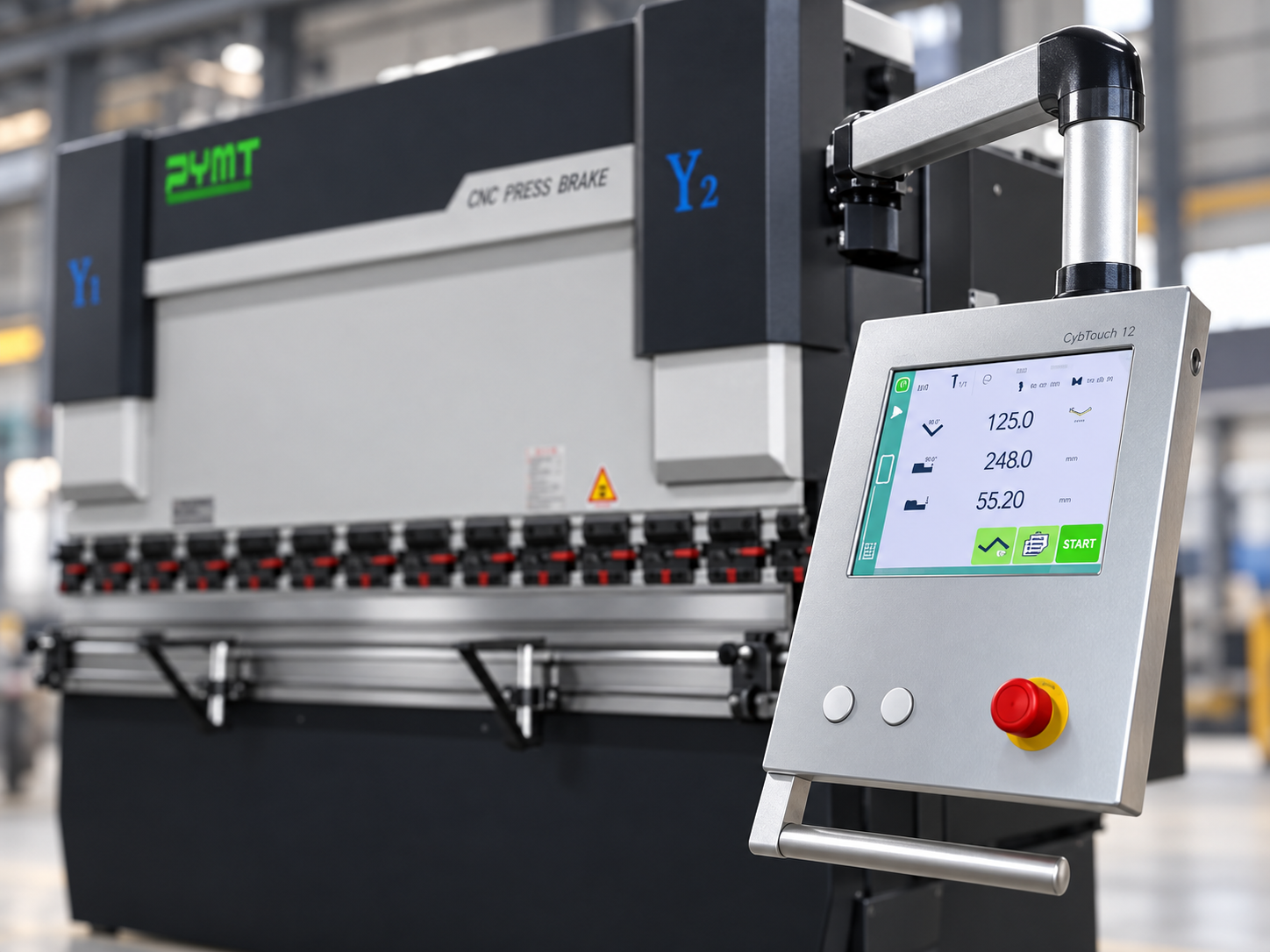
A CNC press brake used for sheet metal bending. Finished flange accuracy depends on more than the programmed backgauge position, so gauge repeatability, workpiece contact and the bending process should be checked separately.
Start with the error pattern
What is actually changing?
Fixed offset
Readings remain tightly grouped but consistently long or short. Investigate the datum, reference and correction state before assuming instability.
Random scatter
Readings move both long and short. Find the unstable mechanical, contact or measurement variable before applying an offset.
Reference-dependent change
The result changes after homing, restart or direction reversal. Preserve that pattern before changing machine values.
Separate Backgauge Error from Bending Error
A finished flange measuring too long or too short does not by itself prove that the backgauge stopped in the wrong place. By the time that dimension is checked, several variables have already affected the part.
Consider a batch where the first parts are acceptable, but later parts begin alternating slightly long and short. One possibility is inconsistent backgauge positioning. Another is that the blanks are not contacting the fingers in the same way. A third is that the gauge position is stable while bend angle or springback is changing the finished geometry.
The stop position changes
If repeated physical checks show that the backgauge does not return to the same location, backgauge repeatability becomes the main diagnostic direction.
The bend result changes
The physical gauge position may remain stable while angle, springback, tooling condition or material response changes the finished flange measurement.
The blank references differently
Burrs, an uneven cut edge, bow, twist, contamination or contact with only one finger can shift the real starting position without any change in the programmed value.
This distinction becomes especially useful when only one part family shows a problem. If several other jobs repeat normally on the same machine, compare the reference edges, material condition and contact method of the problem part before treating the machine as the common cause.
When investigating a press brake length error, always state what was measured: the physical backgauge position, the blank against the fingers or the finished flange after forming. Those measurements answer different questions.
Repeatability Check Before Calibration
A useful backgauge calibration check begins before any calibration value is changed. The first job is to find out whether the gauge can return to the same physical point repeatedly.
Choose one position that can be measured safely and consistently on the actual machine. Use the machine’s documented X-axis reference method and keep the same physical datum for every reading. Do not mix controller X values, a direct gauge measurement and a finished flange dimension in the same dataset. Move the gauge away from the test point, return to the same commanded position and record the result. Repeat the movement several times rather than repeatedly measuring a gauge that has remained stationary.
Position Error
Keep the calculation simple
Position error (ΔX) = measured physical position − commanded position
The sign is only useful if the same datum and measurement convention are used for every reading.
The value of this test is in the shape of the results. Five readings grouped closely together but all short describe a stable offset. Five readings scattered both long and short describe instability. Those two patterns should not lead to the same adjustment.
Keep the individual readings.
Record the commanded position, measured position, direction of error and whether the gauge approached from the same direction. Do not reduce the entire test to an average before looking at the spread.
A practical repeatability record. Use the same datum and measurement method for the full test.
Cycle
Commanded X
Measured X
ΔX
Approach Direction
Homing State
1
Record
Record
Calculate
Forward / reverse
Before / after home
2
Record
Record
Calculate
Forward / reverse
Before / after home
3+
Continue
Continue
Calculate
Keep consistent
Keep consistent
Once a normal same-direction test has been recorded, compare the result after the gauge approaches from the opposite direction where this can be done within the machine’s normal operating procedure. If the measured location depends on travel direction, the evidence deserves investigation before an offset is applied.
Where the machine arrangement allows a meaningful comparison, check the left and right contact positions using the same reference method. If one side behaves differently, that can narrow the investigation toward a finger, carrier, local alignment condition or workpiece contact rather than one global controller value.
Tight grouping + fixed offset
Repeatability may be stable. Investigate reference, datum and correction state.
Wide or irregular scatter
Find the unstable variable before treating calibration as the solution.
Machine-specific specifications are reference limits, not finished-part tolerances.
The ZYC-63T/2500 datasheet used for this reference lists an X-axis maximum distance of 500 mm, a maximum X-axis travel speed of 200 mm/s and X-axis positioning accuracy of ±0.05 mm. That positioning figure describes the backgauge axis specification; it should not be presented as the guaranteed finished flange tolerance because bend angle, springback, tooling, material and workpiece reference can still change the final dimension.
Calibration becomes meaningful only after repeatability is understood. Moving an offset can centre a stable error. It cannot remove random scatter.
Mechanical Checks
When the repeat test shows unstable positioning, the most productive mechanical investigation usually starts at the point where the material touches the machine and works backwards. That keeps the first checks simple and avoids treating every dimensional problem as an internal drive fault.
When only one side looks wrong
Compare the backgauge fingers themselves. Look for chips, dirt or damage on the contact faces and check whether a finger appears displaced relative to the other. If the part contacts one finger firmly but only touches the other intermittently, the measured flange can change even though the driven axis is returning normally.
The blank deserves the same attention. A burr facing the gauge, an out-of-square edge or a bowed sheet can prevent full contact. When a problem follows only certain blanks, rotate the investigation toward the part reference before changing machine settings.
When the error appears after direction reversal
A position that measures differently depending on the direction of approach is useful evidence of possible mechanical play or transmission behaviour. It does not identify the component responsible, but it gives a technician a much stronger starting point than a general complaint that the gauge is inaccurate.
Depending on the machine, movement may be transferred through screws, couplings, belts, gears, racks or another arrangement. Accessible finger carriers, brackets and normal inspection points can be checked for visible movement or signs that something has shifted. Guarded or service-level components should only be inspected under the actual machine documentation and approved isolation procedure.
When the problem began after a collision
A sudden repeat-length deviation immediately after an impact is more useful diagnostic evidence than a gradual dimensional complaint with no known event. Look for changed finger alignment, new witness marks, a bracket that appears to have moved or another visible difference that can be documented without dismantling the machine.
If there is visible damage, abnormal motion or another condition that makes repeated cycling unsafe, stop the test and move to technical assessment. Another data point is not worth creating a larger mechanical problem.
Reference, Homing and Controller Checks
Some repeat-length problems remain stable for an entire run and only appear again after restart, homing or program recall. That pattern deserves a reference-system check rather than an immediate mechanical adjustment.
Measure the same physical test position before and after the machine’s normal homing procedure. If the reference position changes in a repeatable way after homing, keep both sets of readings. Do not immediately remove the evidence by applying a new correction.
Controller
Confirm what the control is commanding
Check that the intended program and bend step are active, that the displayed gauge value is the expected one and that the program has not been copied with an unintended correction.
Corrections
Identify active offsets first
If the control supports stored offsets, compensation or tool-related corrections, establish which values are active before changing them.
This matters in day-to-day production because an operator may compensate for a finished flange while the underlying change is actually bend angle. The corrected program can then look like a backgauge problem when another material batch or tooling setup is loaded.
Controller menus, parameter names and reference procedures vary by machine and control platform. Machine-specific adjustments should therefore follow the documentation for the actual equipment rather than menu instructions copied from a different controller.
If the evidence points toward a controller, drive or reference issue that cannot be verified safely at operator level, CNC Laser Durban’s CNC technical support route is the appropriate next step for submitting the machine and fault information for review.
Diagnostic Table: Read the Pattern Before Changing the Machine
The table below is intended as a quick reference after the first repeat test. It does not declare a root cause; it shows which observation is likely to provide the most useful next piece of evidence.
Backgauge repeat-length fault patterns and the next useful check.
Symptom
Possible Direction
Check First
Useful Record
Same offset on most cycles
Datum, reference, correction value or finger location
Compare commanded and physical position
Target, actual result, error direction, homing state
Readings scatter long and short
Contact inconsistency, looseness, measurement variation or unstable movement
Repeat controlled positioning cycles
Every reading, not only the average
Position changes after homing
Homing or reference relationship
Run the same test before and after homing
Pre-home and post-home measurements
Error changes with approach direction
Mechanical play or transmission behaviour
Compare forward and reverse approaches
Direction of travel and resulting position
Gauge repeats but flange still varies
Bend angle, springback, material response or blank reference
Separate gauge measurement from finished-part measurement
Gauge result, flange result, material and bend condition
Acceptable tolerances, calibration limits and service procedures depend on the actual machine and controller. Use the equipment documentation and onsite verification rather than applying a universal tolerance.
What to Send for Technical Review
A statement such as “the backgauge is inaccurate” gives very little information about where to look next. A useful fault report shows the pattern that led to the concern.
Measurements
Send the commanded gauge position, individual repeat measurements and the number of cycles performed.
Pattern
State whether the result is consistently long, consistently short, alternating or apparently random, and record any effect from travel direction or homing.
Photographs
Show the backgauge fingers, workpiece contact area and blank reference edge. Include both sides where one side behaves differently.
Visible impact marks or a change that appeared after a collision should also be documented.
Include the relevant program setting and note whether the dimension was measured directly at the gauge or only after bending. If the finished flange is varying while the physical gauge position remains stable, include the material and any visible change in bend angle or part condition.
The strongest fault report separates observation from assumption: what was commanded, what was measured, what changed and what stayed consistent.
Next Step
Send the repeat-length evidence before changing the diagnosis
Use the measurements, approach direction, homing result and contact photographs recorded above when requesting a fault review. If the enquiry also involves replacement or additional equipment, include the material, required working length and bending requirements so the equipment discussion can be assessed separately from the existing machine fault.
The objective is to establish whether the next step is calibration, mechanical inspection, controller or reference investigation, workpiece-contact correction, or a review of the bending process itself.
No. Repeatability describes whether the backgauge returns to the same physical position under the same conditions. Accuracy describes how close that position is to the intended value. A gauge can repeat consistently while still carrying a fixed offset.
How can I tell whether the problem is the backgauge or bend springback?
Compare the physical gauge position with the finished-part result. If the gauge continues to return consistently while the finished flange changes with bend angle or material response, investigate the bending process and workpiece reference before correcting the gauge.