
How to Choose a Sheet Metal Bending Machine

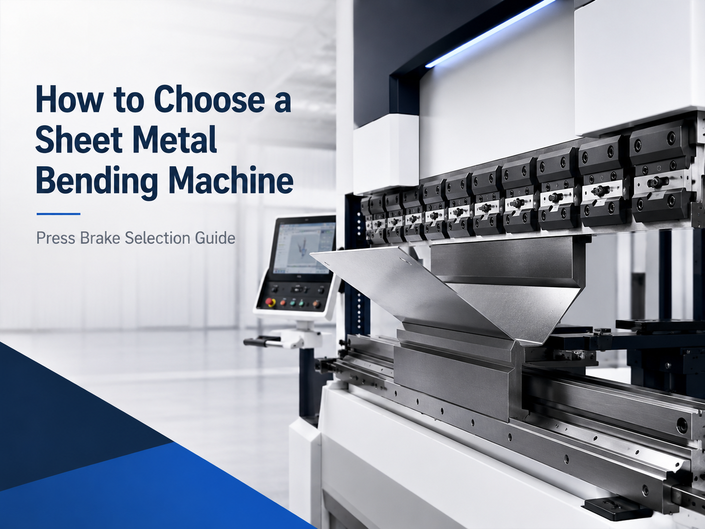
Choosing the right Sheet Metal Bending Machine starts with the parts entering production, not one isolated machine specification. Material grade, thickness, active bend length, flange size, radius, tooling, accuracy, and output must be assessed together. Tonnage, back-gauge movement, control level, safety, electrical supply, and available floor space can then be matched to the work. This approach reduces the risk of limited capacity, slow setups, unsuitable tooling, and installation problems.
A practical selection rule
Start with the material and representative parts, then use real drawings to verify forming force, active bend length, tooling, gauging, and control requirements. Safety, training, power, access, installation, and support complete the decision. Nominal tonnage on its own is never a substitute for an application review.
1. Build the Selection Around Real Production Work
A reliable selection process begins with current and expected parts. Group the work by material, thickness, length, bend sequence, tolerance, and batch size, then record the problems already affecting production: inconsistent angles, difficult handling, slow changeovers, tool marking, or repeated trial bends.
Translate those requirements into machine functions. Required force, usable working length, stroke, open height, throat depth, tooling standard, gauge travel, and control capability should come from representative drawings, with every requested feature tied to a defined production need.
One unusual maximum should not define the complete installation. A long low-volume part may be outsourced, while a thinner high-strength material formed over a greater length may create the more demanding application.
Include these representative parts
- The longest continuous bend
- The thickest and highest-strength materials
- The smallest flange and tightest radius
- The deepest box or most difficult return flange
- The most accurate and most frequently produced parts
- The heaviest blank and most complex bend sequence
A high-mix workshop often gains more from quick setup, segmented tooling, programme storage, and flexible gauging than from maximum cycling speed. In contrast, a dedicated production cell may place greater value on stable tooling, repeatable gauge positions, controlled material batches, and a consistent inspection method.
See a press brake in operation
The video below shows a press brake operating in an industrial setting. It supports an early understanding of part movement and forming action, but final equipment selection still requires drawings, material data, tooling details, and an application review.
2. Define Material, Thickness, and Bend Length
Material information controls much of the selection. Broad descriptions such as “standard steel” are not enough for a dependable force and tooling review. Each important material family should be identified by grade, condition, coating, and thickness range.
Mild steel, stainless steel, aluminium, galvanised sheet, coated steel, and high-strength grades can behave differently at the same thickness. Yield and tensile strength influence forming load and springback. Aluminium alloy and temper can also affect cracking risk and the minimum practical radius.
Record the full thickness range
A maximum thickness does not describe daily work. A useful material schedule records minimum, typical, and maximum thickness for every main grade. This distinction helps balance precise low-force work against occasional heavy forming.
Separate part length from active bend length
Overall part size is not always the same as the active bend length. A large panel may contain one short local bend, while a narrow strip may require one continuous bend over its full length. Drawings should identify the actual contact line between punch, material, and die.
Nominal machine length may also differ from practical usable length. Side structures, guards, clamps, tooling segments, and permitted loading positions can reduce the working area. Long components additionally need enough space for loading, rotation, support, and removal.
The RFQ should not simply state “6 mm maximum thickness and 3 metres maximum length.” It should confirm whether 6 mm must be formed over the full 3 metres or only on short brackets. That difference can materially change the capacity requirement.
Coordinate cutting and bending
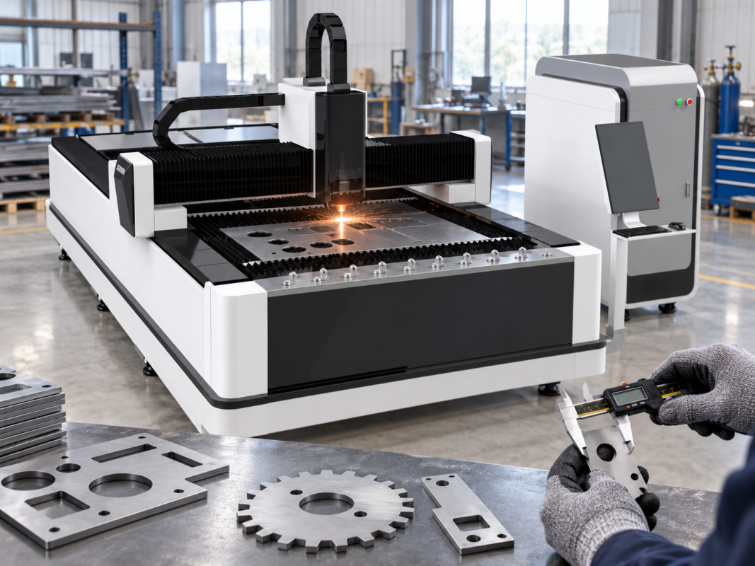
Bending consistency also depends on the incoming blank. Cut accuracy, burr direction, edge quality, flatness, part identification, and material traceability can affect gauge contact and final dimensions. A productive cutting process may create a forming bottleneck when programming, tooling, and handling do not keep pace.
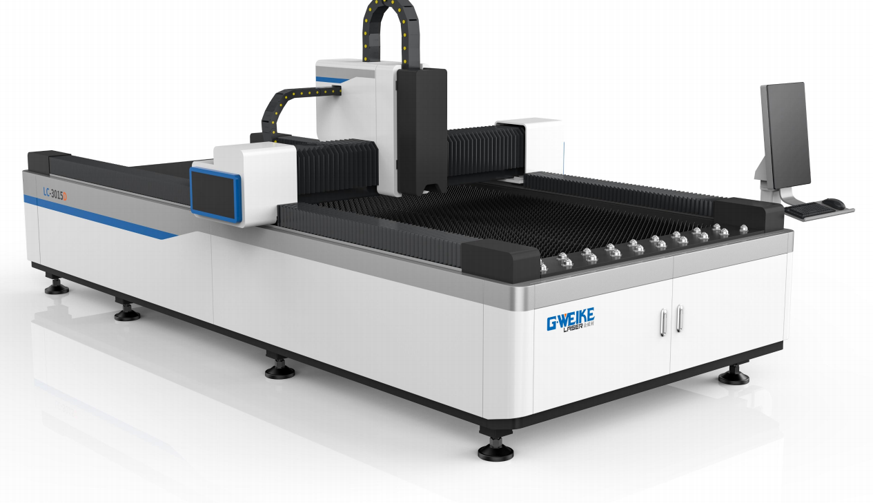
Related upstream equipment: accurate blank preparation can support more consistent gauging and forming.
3. Confirm Tonnage From the Correct Inputs
Tonnage describes available forming force, but the rated figure alone does not confirm suitability. Required force depends on material strength, actual thickness, active bend length, V-opening, punch profile, required radius, forming method, and tool condition.
As thickness increases, resistance to bending rises quickly. A small thickness change can create a much larger increase in force. A different grade, longer bend, narrower opening, or tighter radius may also make a new part substantially more demanding than an older job.
Opening size changes both force and geometry
A narrower die opening can support a shorter flange and tighter bend, but it generally increases load and may leave stronger marks. A wider opening can reduce force, although it may create a larger natural radius and require a longer flange.
That trade-off is why the lowest tonnage is not the only objective. The selected opening still has to support the drawing, material behaviour, surface requirement, flange size, and tool load rating.
Check total force and concentrated load
A short bend can concentrate a large load into a small section of the ram, bed, holder, punch, and die. Even when total required force appears acceptable, the local load may exceed permitted limits. Short-part and off-centre bending should receive a specific load review.
Full-length work creates a different issue. The ram and bed may deflect under load, producing angle differences between the centre and ends. Crowning or another approved compensation method may then be required.
Inputs required for a force review
- Material grade and strength data
- Actual thickness and continuous bend length
- Proposed V-opening and required radius
- Punch, die, holder, and adapter details
- Air bending, bottom bending, or another approved method
- Planned load position and production frequency
Online calculators are useful for early planning, but final capacity needs application-specific data. A useful proposal records the material strength, forming method, opening, expected radius, active length, tool capacity, and operating margin used for the calculation.
4. Match Tooling to Bend Geometry
Tooling is part of the forming system, not a minor accessory. The punch and die affect radius, minimum flange, force, surface marking, part clearance, setup time, and repeatability. They should be reviewed with the machine from the beginning.
Start with radius and flange requirements
The drawing should identify the required inside radius and permitted variation. During common air bending, the finished radius is influenced by material properties and die opening. The punch-tip radius alone does not always define the result.
Tight radii can increase cracking risk in some materials. Grain direction, alloy condition, edge quality, and heat treatment may also matter. A larger radius may reduce load and cracking risk, but it can change the flat pattern and assembly fit.
Check punch shape and collision clearance
A straight punch suits many open bends. Return flanges, channels, and boxes may require a gooseneck or another specialised profile. The complete bend sequence should be checked because a tool may clear the first bend but collide with a later return.
Tool height also affects available space. The upper clamp, punch, die, holder, adapters, and raising blocks form one tool stack. That stack must fit within the available open height while leaving enough room for loading, rotating, and removing the part.
Full-length tools can suit repeated long bends, while sectional tools provide greater flexibility for varied parts. Sectional arrangements still require correct alignment, secure clamping, organised storage, and clear load ratings.
Long bends may also need crowning to manage deflection. Crowning cannot correct worn tools, uneven material, poor alignment, or unstable gauge contact, so it should form part of a wider process-control plan.
Before order placement, make sure the required profiles are actually available, the clamping system accepts them, and every component in the tooling stack carries an adequate load rating.
5. Select the Back Gauge and Control Level
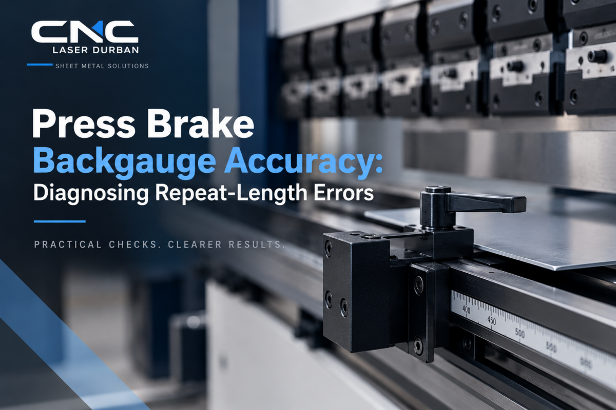
The back gauge positions the blank before each bend. Its travel, axes, fingers, speed, and control method influence setup time and dimensional consistency. More axes are useful only when the component geometry needs them.
The X-axis normally controls front-to-back flange depth. An R-axis moves the fingers vertically, while Z movement changes their position along the working length. Independent movement may help with different part widths, asymmetric work, or frequent setup changes.
Basic control or CNC control?
Basic numerical control can suit straightforward channels, stable setups, and limited bend sequences. It may control cost and simplify routine work, although setup depends more heavily on process knowledge and written instructions.
CNC control becomes more valuable with multi-bend parts, short batches, several gauge positions, frequent programme recall, and regular tooling changes. Graphical programming can support sequence planning, while stored jobs can reduce repeated setup work.
A programmed position is useful only when the blank contacts the fingers consistently. Cut-edge quality, burrs, slots, tabs, existing bends, and sheet sag can all affect gauging. Representative parts should therefore be reviewed whenever possible.
Finished accuracy also depends on material variation, springback, tool condition, crowning, gauge contact, cutting accuracy, and handling. Published axis repeatability should not be treated as a guaranteed component tolerance.
6. Review Output, Safety, Training, and Site Requirements
Production capacity depends on more than ram speed. Material retrieval, tool changes, programme loading, gauge setup, part rotation, inspection, stacking, and internal transport can consume a large share of each shift.
Output should therefore be estimated from representative parts. Record bends per component, normal batch size, setup frequency, handling method, inspection time, and upstream cutting volume. A fast press may remain underused when handling or tooling changes create the real bottleneck.
Plan safeguarding around the real work
Press brakes create crushing, trapping, cutting, and movement hazards. Safeguarding and approved procedures must form part of the specification. Hazards can exist between punch and die, around moving gauges, beside large sheets, and during tool changes.
The safety arrangement may include suitable front protection, emergency stops, guarded foot controls, rear and side protection, controlled access, and safe setup modes. The correct arrangement depends on the machine, part, operating mode, and site risk assessment.
South African workplace planning should also consider the applicable Driven Machinery Regulations, 2015. Site-specific obligations and compliance decisions should be confirmed by competent safety personnel.
Include training in the acquisition plan
Training should cover safe start-up and shutdown, operating modes, emergency procedures, tool installation, load limits, programme creation, gauge setup, trial bending, correction, cleaning, and fault reporting. Maintenance personnel may require different instruction from production personnel.

Service module: practical training scope should be confirmed for the selected machine and application.
Verify power, access, and floor space
Record the required voltage, phase, frequency, connected load, protective devices, and any compressed-air requirement in the installation scope. A qualified electrical review can then confirm site compatibility before the machine arrives.
Overall machine dimensions do not describe the complete cell. Service access, electrical cabinets, tool storage, front supports, part rotation, finished-part stacking, safety zones, and pedestrian routes all require space.
The delivery route also needs checking. Door dimensions, turning space, roof clearance, unloading area, lifting capacity, floor condition, and foundation requirements can determine whether installation is practical.
Plan maintenance access
Service points should remain accessible after cabinets, supports, and material racks are installed. Maintenance intervals should follow the supplied documentation.

Service module: setup, diagnostics, maintenance planning, and support scope should be confirmed for the proposed installation.
7. Prepare a Complete RFQ and Compare Proposals
A strong RFQ reduces assumptions before configuration and pricing begin. Submitting only a requested tonnage and working length transfers too much interpretation to the equipment team. Different proposals may then be based on different materials, openings, tooling, or service assumptions.
A better RFQ includes representative drawings, material data, production targets, site information, and a requested quotation format. It should also ask for clear assumptions, exclusions, included tooling, safeguarding, installation duties, training, and support scope.
Ask for a documented application review
A documented application review needs to show the assumed material strength, forming method, die opening, expected radius, tool load, gauge approach, crowning method, and handling requirements. Any part that needs a special tool, sample bend, or separate approval should be identified before the order is released.
Compare tooling by specification rather than item count. Tool standard, profile, precision, section lengths, load rating, clamps, adapters, storage, and replacement availability all affect the real installed cost.
Installation responsibilities belong in the written scope as well. State who handles unloading, positioning, lifting, anchoring, electrical connection, levelling, commissioning, training, and acceptance testing so these costs and duties are not discovered at delivery.
Compare total fit, not purchase price alone
A weighted comparison can assess application fit, tooling fit, control fit, safety, installation, training, support, documentation, delivery scope, and commercial terms. A lower initial price may become less attractive when essential tools, site work, or training are excluded.
Once the production pack is ready, use the contact page to request an availability check. Configuration, included scope, current supply status, and technical suitability should be confirmed before approval.
Frequently Asked Questions
How much tonnage is required?
Required force depends on material strength, thickness, active bend length, V-opening, radius, tooling, and forming method. Final capacity should come from an application-specific review that also checks local machine and tool loads.
Should working length equal the longest part?
Not always. The critical dimension is the longest continuous bend that must fit within the usable tooling area. Overall part size still matters for loading, rotation, gauging, support, and removal.
Is CNC control necessary for every press brake?
No. Basic numerical control can suit simple repeated parts. CNC becomes more useful with frequent changeovers, multi-bend components, several gauge positions, programme recall, or demanding repeatability.
Which tooling should be ordered?
Tooling should follow material range, radii, minimum flanges, part clearance, surface finish, and load requirements. Representative drawings should define punches, dies, segments, clamps, adapters, and storage needs.
What determines bending accuracy?
Accuracy depends on material variation, springback, cutting quality, tool condition, ram movement, crowning, gauge contact, handling, and inspection. Axis repeatability alone does not guarantee finished-part tolerance.
What should be prepared before installation?
Confirm access, lifting capacity, floor condition, electrical supply, service clearance, material space, tool storage, safety zones, unloading duties, commissioning scope, training, and acceptance criteria before delivery.
What to Prepare Before Requesting a Press Brake Quote
A successful press brake decision begins with accurate production data. Material strength, thickness-and-length combinations, bend radius, flange geometry, tooling, gauging, output, safety, training, power, access, and maintenance must work as one system.
Before selecting a Sheet Metal Bending Machine, complete three practical actions:
- Prepare representative drawings covering frequent work and the most demanding geometry.
- Request a documented review covering force, tooling, gauging, control, safety, installation, and training.
- Compare complete scope, including tools, site work, documentation, support, and confirmed availability.
Request a Press Brake Application Review
Send material grades, thickness ranges, active bend lengths, representative drawings, required radii, output targets, existing tooling information, power supply, and site constraints. That gives the sales and technical team enough information to discuss configuration, training, support scope, installation needs, and current availability around the work you actually plan to bend.



2 thoughts on “How to Choose a Sheet Metal Bending Machine”