If a seam opens as the clamps close, or a welded box moves out of shape when the clamps are released, changing laser settings may not solve the problem. The parts first need to sit in the same position every time, with a consistent gap and enough access for the handheld welding head. Good laser welding fixture design starts with how the parts fit together and where they are located—not simply how firmly they are held.
For work being assessed around the LCW Series laser welding system, fixture decisions should be reviewed with the actual joint geometry, material condition and normal production variation. If components enter the fixture differently from one cycle to the next, changing welding settings alone cannot create consistent fit-up.
The practical goal is controlled restraint: locate the parts from known references, hold the intended relationship without unnecessarily forcing the assembly, verify the gap before welding and understand what changes when the finished part is released.
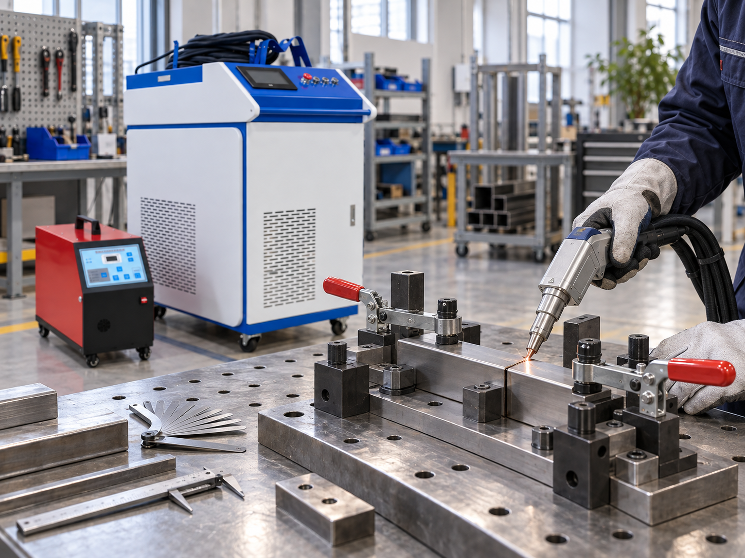
Fixture design starts with repeatable location and fit-up. The clamps should hold the fabricated assembly against defined references while leaving the joint visible and accessible.
What the Fixture Must Control
A fixture needs to keep five things under control: part position, joint gap, joint angle, repeat positioning and movement during welding. They affect one another. A part can feel solid in the clamps while the seam is still misaligned. Or the first assembly can fit well, only for the next one to sit differently in the same fixture.
Part position comes from fixed locating surfaces or features. These establish where the workpiece belongs before the clamps close. The clamps should normally hold it against those references, not decide its position each time.
Joint gap and angle determine what the welding head is actually being presented with. Two components may appear to be touching but still be twisted, lifted or angled differently from the intended joint condition. That matters particularly on corners, lap joints, fabricated boxes and assemblies made from formed sheet.
Repeat positioning is what turns a workable fixture into a production fixture. A practical check is to load a representative part, record the joint position, remove it and load it again. If the fit-up changes noticeably before welding has even started, the fixture or incoming component condition needs attention.
Thermal movement is the fifth control. Welding introduces heat and shrinkage, so the design has to decide what must remain restrained and where some movement can be tolerated. Trying to lock every surface completely is not automatically the most stable approach.
Datum and Clamp Placement
Start with the drawing: which faces, edges or features determine whether the finished assembly will fit its intended use? Those are the references worth considering first. They also need to be consistent enough on the incoming parts to locate each assembly the same way.
For a fabricated box or enclosure, for example, a large flat surface may look like the obvious datum. That is only useful if the surface is actually stable enough before welding. A flange affected by forming variation, a cut edge carrying a burr or a face sitting on debris can shift the complete joint even though every clamp appears to close correctly.
A useful test: separate locating from clamping.
Ask which fixed surfaces tell the component where it belongs before the clamps are fully tightened. If changing clamp pressure changes the intended joint position, the clamp may be doing too much of the locating work.
Clamp direction matters as much as clamp location. Ideally, the clamping action seats the component toward the chosen reference rather than dragging it sideways or lifting another area of the assembly. If closing one clamp causes another part of the seam to open, the sequence or restraint pattern needs review.
The fixture also has to preserve welding access. A clamp close to the seam can help local fit-up, but the operator still needs visibility and a workable path for the handheld head. If the clamp forces a major change in working angle halfway along the seam, static rigidity has been gained at the expense of process consistency. Exposed metal surfaces and clamp positions must also be considered in the laser safety assessment, including possible reflected radiation.
The right arrangement depends on what is being welded. A workshop changing between several part sizes may benefit from adjustable stops and modular clamps. A repeated production assembly may be easier to locate with dedicated stops. If thin sheet lifts beside the seam, look at local support and the direction of clamping; if the weld runs into a box corner, check whether the handheld head can actually reach it. Trial parts should confirm that the chosen arrangement closes the joint without forcing parts beyond acceptable tolerances.
This is why the fixture clamping sequence should be repeatable. Where the order of closing clamps affects fit-up, that order should be documented and validated rather than left to operator habit.
Gap Control Before Welding
Joint gap control starts with a simple question: why does the seam open in the first place? The cause might be an uneven cut edge, a formed flange sitting at the wrong angle, local bowing, a burr or debris on a fixture contact surface. These are fit-up problems to inspect before changing welding parameters.
A fixture cannot reliably correct unlimited upstream variation. If one part enters the fixture naturally while another must be pulled heavily into place, they do not have the same starting condition even if the visible gap looks similar after clamping.
Check the gap at the same points each time
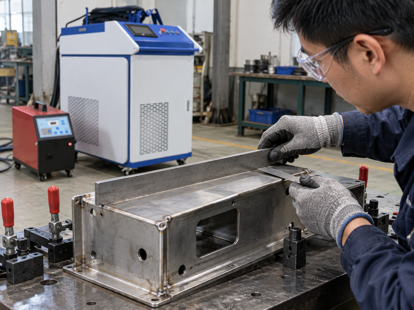
Instead of writing only “gap OK,” mark the same locations along the seam for each trial—for example, near the start, middle and end where the geometry allows. Use a suitable feeler gauge, controlled setup shim, go/no-go reference or other repeatable method. The point is to see where the joint changes, not just whether one spot looks closed.
The accepted fit-up tolerance should come from the drawing, process requirement or actual validation for the application. There is no universal gap value that is appropriate for every material, thickness, joint geometry or equipment configuration.
Check the joint after the fixture is loaded, not only while the components are loose. The seam should remain accessible so local gap, misalignment or part lift can be identified before welding.
Watch what happens when the clamps close. If the gap closes at one end but opens at the other, look at the clamp direction and locating points. If the same corner needs to be pushed into place on every cycle, check whether it is properly supported. If only some parts need that push, compare their incoming dimensions before blaming the fixture alone.
Temporary shims can be useful during development when they help identify the source of variation. They become a warning sign when each production part needs a different improvised spacer to make the joint close.
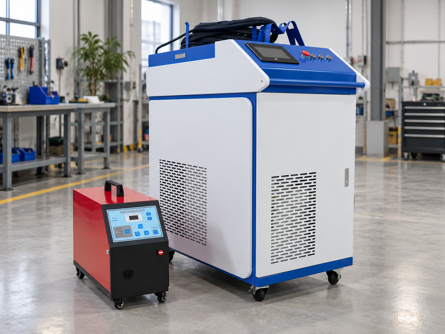
For equipment context, CNC Laser Durban groups the relevant systems under its Fibre Laser Welding, Cleaning & Cutting Machines category, which leads into the LCW Series model information. The equipment decision should still be made against the real part, joint and normal production fit-up.
Managing Distortion with Sequence and Restraint
Welding distortion control is easier to troubleshoot when you know when the shape changed. Did the panel lift as the clamps closed? Did the corner move during welding? Or did the box look straight in the fixture and twist only after release? Those outcomes point to different combinations of part geometry, heat, weld order and restraint.
Where the joint layout allows it, the welding sequence can be tested to avoid concentrating shrinkage in one direction. Depending on the assembly, that may mean alternating corresponding weld locations, dividing a long seam into controlled sections or changing the order in which subassemblies are joined.
There is no single sequence that works for every assembly. A thin panel attached to a rigid frame behaves differently from two similar sections being joined together. The fixture also influences the result: a nominally balanced sequence may still produce uneven movement if one area is heavily restrained and another is free to move.
Distortion diagnosis
Measure the same feature at four stages
01 Loaded Record the natural position before full restraint.
02 Clamped Check whether the fixture itself moves the component.
03 Welded & held After cooling to a defined inspection condition, measure while still restrained.
04 Released Measure the final free-state condition.
If the dimension changes between Loaded and Clamped, investigate how the fixture is seating or forcing the part. If it changes during the welding cycle, examine heat input, shrinkage, support and weld order. If it looks correct while held but changes after release, restraint may have been hiding the movement. Compare held and released measurements at the same defined cooling and inspection condition so a temperature difference is not mistaken for release movement.
More clamping force is therefore not automatically better. Excessive restraint can make a part appear stable during welding while transferring the problem into residual stress or post-release movement. The appropriate restraint and release condition should be established on the actual assembly rather than from a universal rule.
Fixture Review Checklist
When one sample looks good and the next does not, a simple setup record helps explain why. Use this checklist to capture what was actually different—not just whether the finished weld passed inspection.
Drawing
Record the revision and identify the dimensions that control the joint and finished assembly.
Datums
Mark the locating surfaces and confirm that the component is fully seated against them.
Clamp points
Record clamp locations and closing order. Note any point where the part lifts, shifts or opens elsewhere.
Gap
Measure at named positions so that the same locations can be checked on the next trial.
Weld path
Confirm full access along the seam before welding begins, including start, finish and changes in direction.
Sequence & restraint
Record the weld order actually used and which areas were deliberately held or allowed to move.
Inspection
Use the same measurement points before welding and after release so dimensional change is traceable.
Where practical, change one meaningful variable at a time. If the datum arrangement, clamp sequence, incoming part condition and weld order are all changed together, a better result does not reveal which change actually produced the improvement.
Common Fixture Mistakes
Over-constraining the assembly
If one part drops into the fixture and the next has to be forced into place, check whether locating points are fighting each other or reacting to normal part variation.
Using clamp force to repair poor fit-up
Pulling mismatched parts together can make the pre-weld gap look smaller without solving the dimensional variation that created it. The difference may return during welding or after release.
Placing clamps without checking the full weld path
If the welding head has to be tilted awkwardly to clear a clamp, the fixture may be holding the part well but making a consistent weld path harder to maintain.
Using unclear datums
If the component can be loaded against different surfaces and still appear to fit, repeat positioning will depend too heavily on operator judgement.
Treating one good sample as proof
Reload the fixture and test representative production parts. One acceptable weld does not show whether normal component variation will reproduce the same joint condition.
Checking distortion only after every seam is complete
Intermediate measurements can show which weld, clamp change or release step starts the movement. That evidence disappears when inspection begins only after the assembly is finished.
Once the fixture condition is understood
Use Representative Parts When Evaluating the Welding System
Machine evaluation becomes more useful once the part can be positioned consistently and the normal production gap is understood. A representative sample should reproduce the actual material, joint type, access and fixture condition rather than using a specially prepared part that removes the fit-up problem found in production.
When considering the LCW Series for this work, assess it with the material, thickness, joint type and access conditions the operator will face in production. A clean weld on a specially prepared sample does not establish that everyday cutting, forming and fixture variation are under control.
What to Send for Sample-Test Review
A photograph of a finished part that has twisted or pulled out of square shows the result, but not when the movement began. To make a sample review useful, show the fit-up before welding, the way the part sits in the fixture and what changes after release.
Part information
Current drawing and revision
Material and thickness
Joint type and weld location
Allowed or measured gap
Fixture and result
Overall fixture photograph
Close views of locators and clamps
Marked distortion location
Photographs of the welded sample after release
If the sequence may be part of the problem, include the current weld order. Mark where dimensions were checked and photograph those same points before welding and after release where possible.
That comparison helps separate a part-supply or locating problem from a welding or release problem. It also makes the next trial more useful: the team can change one suspected cause and see whether the finished dimension improves.
Frequently Asked Questions
Which datums should a welding fixture control first?
Prioritise references that establish the important functional position of the assembly and are reasonably repeatable on incoming parts. Clamps should normally seat the components against those references rather than determine position themselves.
Is tighter clamping always better?
No. Excessive force can deform thin components, hide poor fit-up or hold dimensional change that becomes visible only after the fixture is released. Use enough restraint to seat and control the part, then verify the free-state result.
How can joint gap variation be reduced?
Check incoming cut and formed dimensions, keep locator surfaces clean, establish repeatable loading and measure the seam at fixed positions. If clamp force is the only reason the gap closes, investigate the incoming geometry and fixture arrangement rather than simply adding more restraint.
How should welding sequence work with the fixture design?
The fixture should maintain the required references while leaving clear access for the intended sequence. Sequence trials should then use the same loading, gap and inspection conditions so any change in distortion can be compared meaningfully.
When is a sample weld worth doing?
Sample testing is particularly useful when fit-up varies, a new fixture or weld sequence is being introduced, dimensional movement is affecting acceptance or the actual part has not yet been evaluated under representative fixture conditions.
Prepare the next test around evidence
Send the Part, Fixture and Distortion Details for Review
If a gap keeps opening or a finished assembly changes shape after unclamping, send the drawing and a few marked photographs showing the joint, fixture and affected area. Include material, thickness and the measured gap so the application can be assessed against real production conditions.
The next step is to identify whether the parts, locators, clamping or weld sequence need closer testing—and what should be measured on a representative sample. The goal is a repeatable result within the job’s acceptance requirements, not an unsupported promise of zero distortion.






One thought on “Handheld Laser Welding Fixture Design: Controlling Gap and Distortion”