Two workshops can cut the same plate thickness yet see different results at the edge. The numbers alone rarely explain why. A useful CNC plasma cut chart setup connects amperage, speed and torch height to the power source, consumables, material and process conditions behind them.
For a CNC Plasma Cutting Machine, the power-source and torch documentation gives the starting point. A shop test shows whether that starting point delivers a stable, repeatable cut with the material and consumables actually in use.
The chart becomes useful when it explains what happened, not just which values were entered. Keeping a known baseline and changing one condition at a time makes a better edge—or an unexpected defect—easier to interpret.
A useful cut chart stays tied to the actual machine configuration rather than becoming a generic thickness-and-speed table.
What the chart is really recording
A setting only means something when its operating condition is known
Machine condition
Power source, torch, consumables and process supply.
Programmed inputs
Amperage, travel speed, pierce height and cut height.
Observed result
Penetration, cut-face behaviour, dross and repeatability.
Why the Power Source and Consumables Come First
A cut chart may look precise while describing a different plasma system. Its starting values only make sense when they match the fitted power source, torch and consumables. Approved current ranges, process combinations, gas or compressed-air requirements and cutting sequences depend on that particular configuration.
For example, two machines working on similar plate may use different nozzle and electrode combinations. A chart copied between them can hide that difference, making an apparently sensible speed or amperage adjustment difficult to interpret.
If the material thickness, fitted consumables or plasma source is unknown, there is no dependable reference against which to judge the next speed or height change. The uncertainty lies in the setup, not necessarily in the programmed number.
Keep the machine configuration identifiable when recording a shop baseline.
Start with what is physically installed
The chart should describe this setup, not an abstract plasma process
Consumables can look similar while being specified for different operating conditions. An amperage entry on its own therefore misses a critical part of the picture: which nozzle and electrode produced that result.
The same applies to air or gas supply. When its condition falls outside the plasma system’s requirements, changing travel speed or torch height may disguise the instability rather than explain it.
Amperage Is a Starting Condition, Not a Guess
Plate thickness helps narrow the process choice, but it cannot establish a reliable amperage by itself. The usable starting value comes from the fitted power source and consumable combination, so the first test has a defined reference rather than an estimated number.
The same material may have more than one documented process option. Combining the current from one option with the consumables or speed from another creates an unverified setup, even if each number looks reasonable on its own.
With amperage held steady, changes in edge quality during a speed or height test are easier to understand. Alter current and travel speed together, and even an improved cut leaves an unanswered question: which adjustment made the difference?
The starting point still matters.
The documented starting amperage and the setting eventually accepted after shop testing are not always the same thing. Preserving both makes the result easier to revisit.
What Travel Speed Reveals at the Cut Edge
A straight test cut often tells more about travel speed than a complex nest. With fewer corners and short features influencing the result, it is easier to compare the actual edge against the starting speed given in the process documentation.
When material, consumables, amperage and height remain the same, a controlled speed change can be judged against visible evidence: full penetration, consistent kerf, cut-face drag and the amount of material attached underneath. One poor edge does not identify a single cause; a repeatable difference between comparable cuts is much more informative.
Penetration
Does the arc continue to cut through the material consistently along the test path?
Kerf consistency
Does the cut remain visually stable, or does the result change along otherwise similar geometry?
Cut face
Record the visible drag pattern and its direction of change rather than labelling the sample only “good” or “bad”.
Underside condition
Note changes in attached material or dross, but do not assume one symptom proves a single cause.
If two comparable cuts made at the same settings show different penetration or underside dross, another speed adjustment will not explain the variation. Consumable condition, air supply or height-control behaviour may be the more useful place to investigate.
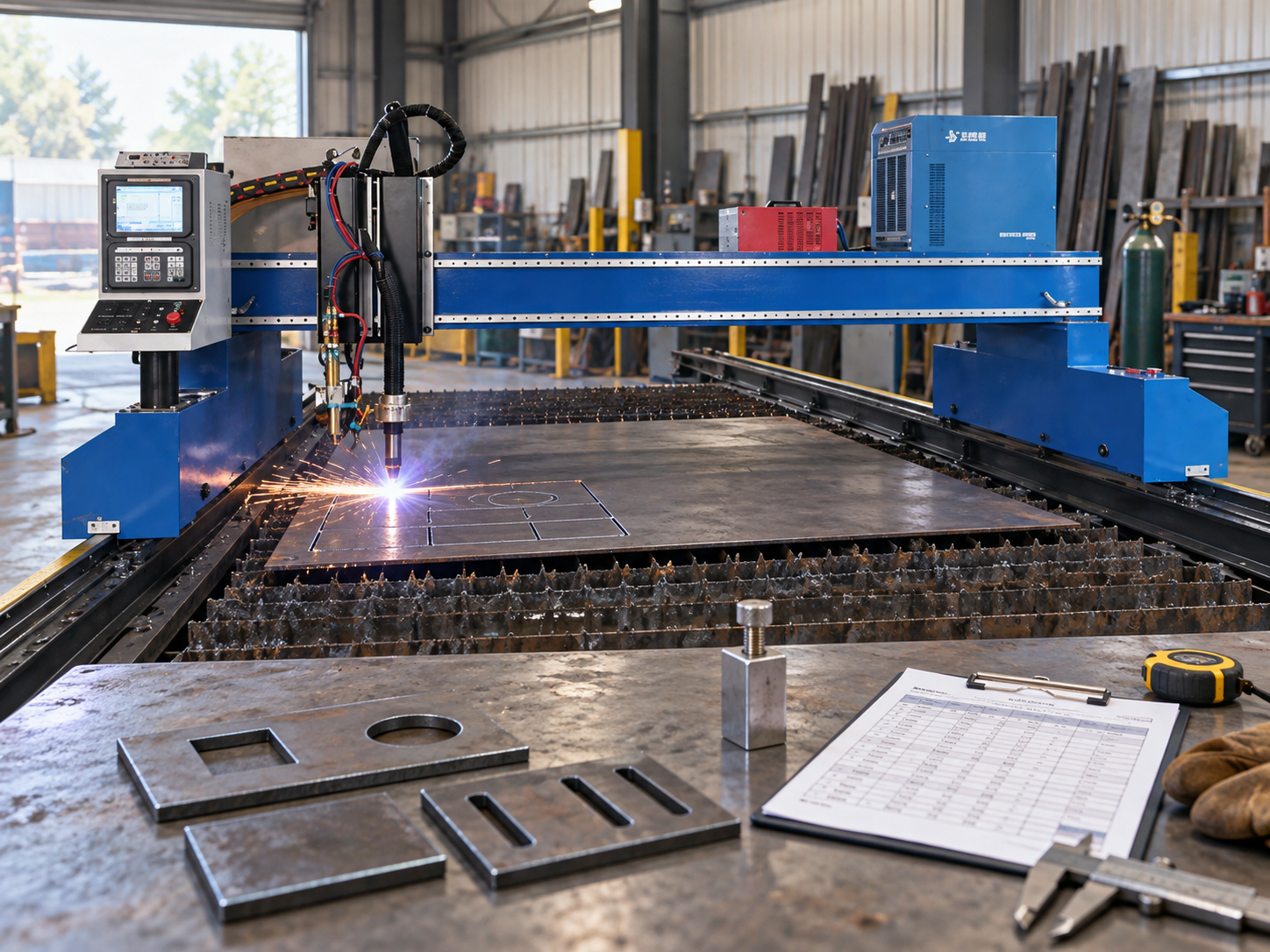
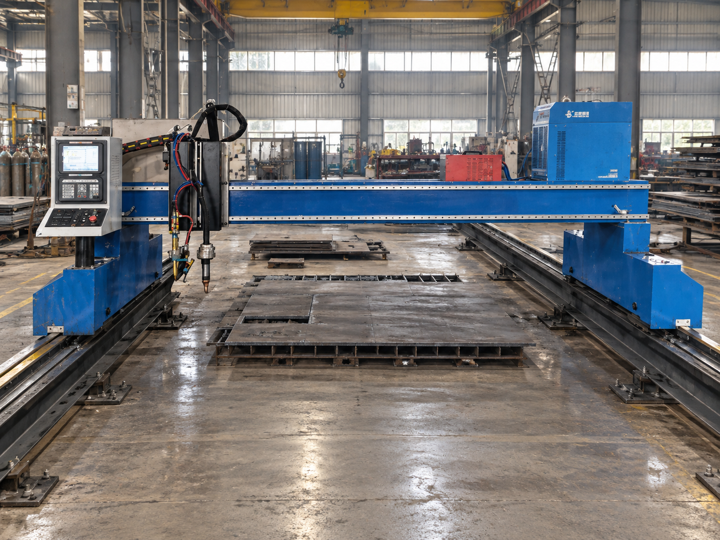
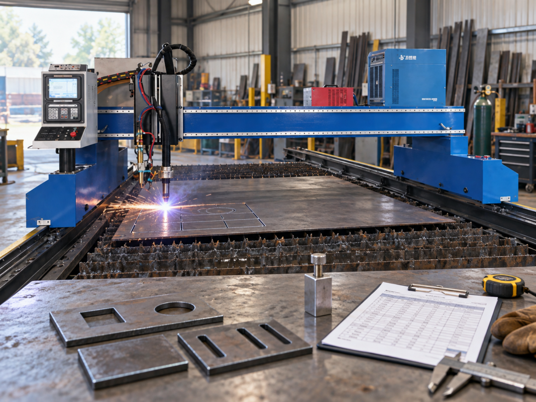
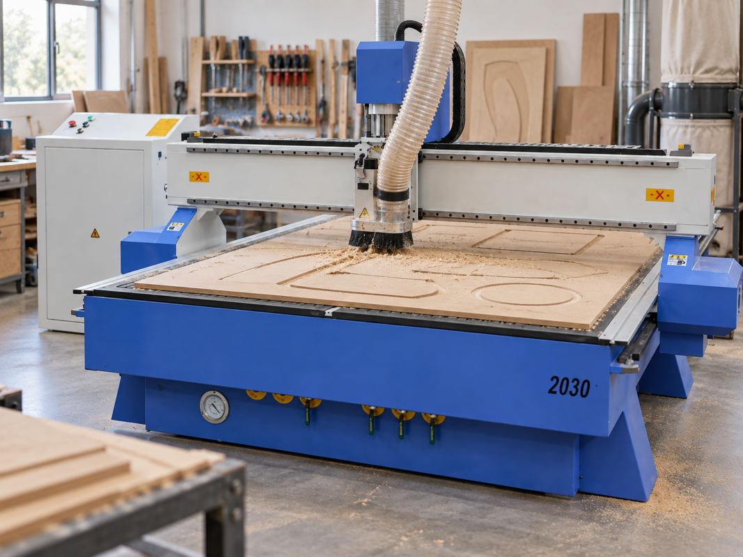
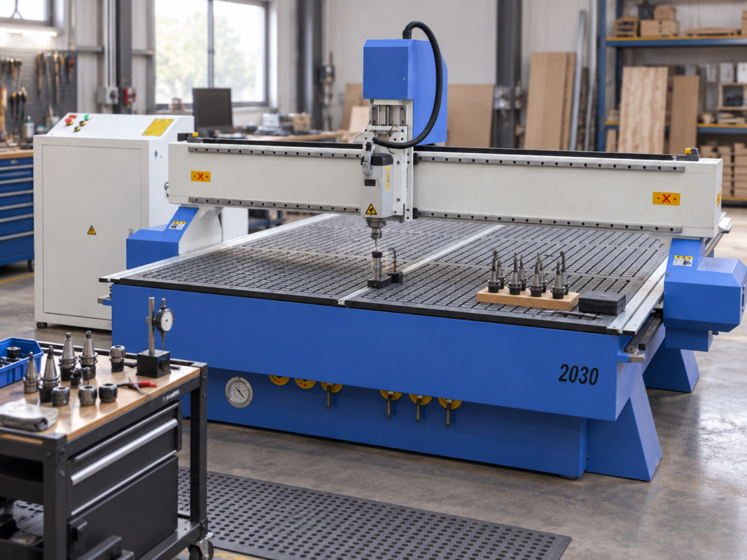
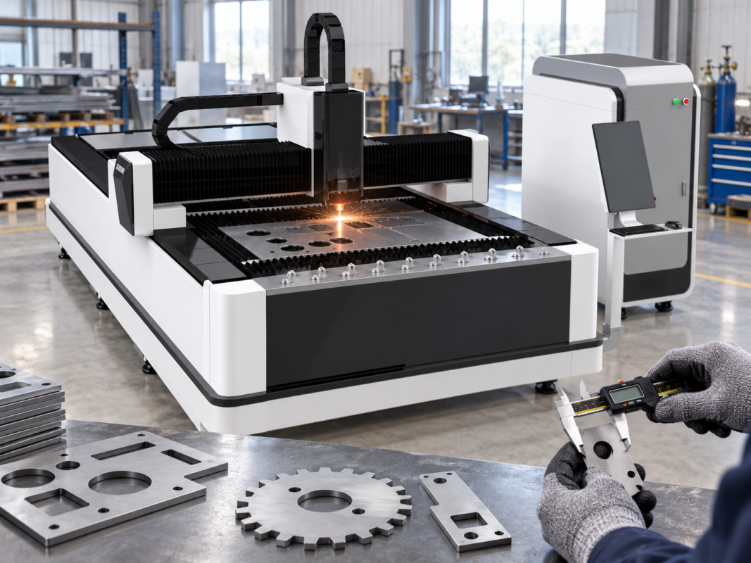
The LM40120HD gantry plasma cutting machine shown here gives the equipment context for these images, not a universal set of cutting values. Applicable process data still depends on the installed plasma source, controller and supplied configuration.
Torch Height and Pierce Sequence
Torch height is easy to oversimplify because piercing and cutting are different stages of the same operation. Pierce height applies while the arc starts and penetrates the plate. The torch then moves to cut height, where a height-control system may regulate its distance from the work during the cut.
Controllers describe that sequence differently. Sensing position, pierce delay, transition, cut height, arc voltage and height-control enable may appear as separate settings, so labels copied from another controller are a poor substitute for the installed machine’s documentation.
Stage 01
Pierce
Record the pierce height and the relevant sequence used while the arc starts and penetrates the material.
Stage 02
Transition
Confirm how the control moves from the piercing condition to the intended cutting position.
Stage 03
Cut and height control
Record cut height and, where applicable, the arc-voltage or other height-control condition used during the test.
Machine photographs provide useful configuration context, but pierce height, cut height and height-control values must still be verified from the actual equipment and controller.
Build a Shop Cut-Chart Record
A clean test cut is only useful as a reference if the workshop can reproduce it later. Saving amperage and speed without the fitted consumables, height-control condition and observed edge quality leaves too much of the original setup unexplained. The record below keeps those details together.
Record
What belongs in the shop chart
Material / thickness
Material description and actual thickness used for the test.
Power source
Exact installed plasma source or identification needed to select the correct process data.
Consumables
Nozzle, electrode and other process parts needed to identify the fitted setup.
Amperage / speed
Starting values plus any later setting accepted through controlled validation.
Pierce / cut height
Keep the two stages separate, together with the relevant height-control state.
Arc voltage
Reference or control value where the installed system uses it.
Observed result
Penetration, kerf consistency, cut-face behaviour, underside condition and repeatability.
Date / operator
Enough traceability to compare the result after maintenance, consumable replacement or process changes.
A comment like “better” says little about what actually improved. “Full penetration maintained; underside attachment reduced; repeat sample matched” gives the next operator something specific to compare.
One-Variable-at-a-Time Validation
An improved edge is difficult to learn from when amperage, speed and height have all changed at once. A controlled comparison works because the effect of each adjustment can be judged separately.
01
Save the baseline
Record the exact starting condition before making the first change.
02
Change one input
Repeat the same geometry with only the variable being investigated changed.
03
Repeat before accepting
A promising result becomes useful only when the same setup can reproduce it.
A better edge is worth keeping as the next baseline when the improvement repeats on a comparable cut. If quality worsens, the previous condition remains a clearer reference than a series of compensating adjustments.
This also helps separate plasma behaviour from machine-motion behaviour. A stable straight test combined with inconsistent small features may indicate that the next investigation belongs somewhere other than the basic amperage, speed and torch-height baseline.
When to Stop Tuning and Check Hardware/Consumables
There is a point at which more tuning produces less useful information. When identical settings give noticeably different cuts, or a controlled change has no consistent effect, the cut chart may no longer be the main problem.
Move the investigation back to the machine
When the machine, not the numbers, needs attention
Confirm that the installed consumables are the intended parts and inspect their condition.
Check torch assembly against the applicable equipment information.
Verify the process gas or compressed-air condition and work connection.
Confirm that height sensing and machine movement are repeatable.
Resolve inconsistent hardware or process behaviour before continuing fine adjustment.
Persistent bevel, dross or other edge defects deserve their own diagnosis. A useful cut chart preserves a proven starting point; it cannot make worn consumables or an unstable machine behave like a sound setup.
Frequently Asked Questions
What equipment information should be confirmed before building a cut chart?
Confirm the plasma power source, torch and consumables, material and thickness, process gas or air requirements, and the controller or torch-height-control system. These determine which process information is relevant to the test.
Should amperage and travel speed be changed at the same time?
No. Use amperage as a verified starting input for the installed power source and consumables. Then evaluate travel speed while keeping amperage fixed. Changing both together makes the result much harder to interpret.
Are pierce height and cut height the same?
No. They apply to different stages of the cutting sequence and should be recorded separately. Exact terminology, values and transition behaviour depend on the installed controller and plasma system.
How should validated cut-chart settings be recorded?
Record the material, thickness, power source, consumables, amperage, travel speed, pierce height, cut height, height-control condition, observations, date and operator. Keep the previous proven baseline instead of overwriting it.
When should parameter tuning stop and hardware be checked?
Stop when identical settings produce inconsistent results, controlled changes no longer create a logical response, or the process becomes unstable. Check consumables, torch assembly, process supply, work connection and height-control behaviour before continuing.
Before changing another parameter
Build the Next Test Around the Actual Plasma Setup
A useful setup review starts with the material and thickness, the actual plasma power source and controller, and the consumables fitted to the torch. Current amperage, travel speed, pierce height, cut height and any arc-voltage setting give that information practical context.
Photographs of the cut samples can reveal what the settings alone cannot. Together with the documented starting values and a note of what changed during testing, they provide a sounder basis for discussion than a generic cut chart from another machine.
Useful information to send:
material and thickness · plasma power source · controller · consumables · amperage · travel speed · pierce height · cut height · cut-sample photos