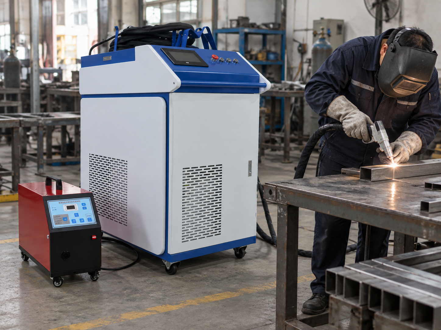
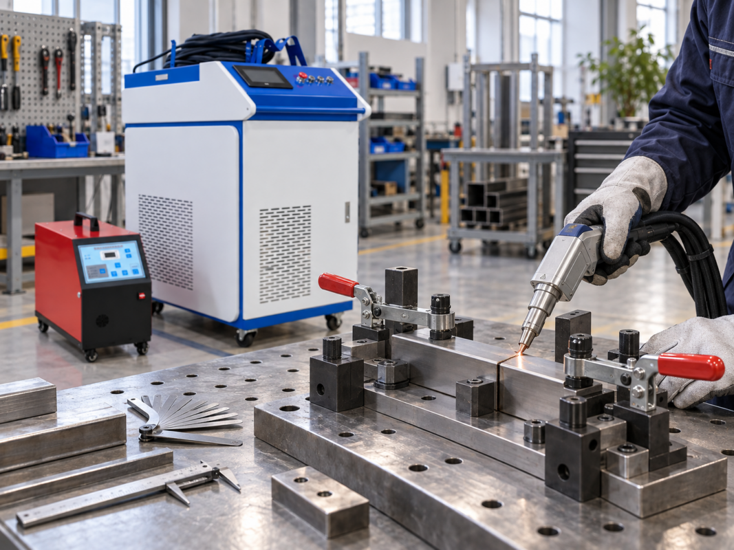
Wire feed cannot be tuned in isolation. On a Handheld Laser Welder, the useful setting depends on the joint, material, thickness, filler wire diameter, fit-up, heat input and travel speed working together.
The practical goal of laser welder wire feed settings is not to find one number that can be copied from job to job. It is to make the filler enter the active molten pool consistently, produce the required bead without unnecessary build-up or underfill, and remain repeatable when the same joint is welded again.
In practice, the most useful clue is what the wire is doing at the joint before the feeder number is changed. Machine-specific units, allowable ranges and controller functions should still be confirmed against the actual equipment documentation and verified on representative material.
Wire-feed tuning should be judged at the joint, not from the feeder display alone. The machine, filler wire and workpiece conditions give the feeder value its context.
Inputs Before Changing Wire Feed
Before changing laser welding wire speed, it helps to keep the surrounding conditions as stable as possible. If fit-up, hand travel or physical wire delivery changes at the same time, a new setting can appear to solve a problem that actually came from somewhere else.
A useful baseline does not need a long parameter sheet. It needs enough information to explain why one test behaved differently from the next.
Joint and fit-up
Whether the weld is butt, lap or fillet changes how the filler reaches the pool. Joint consistency matters too, because filler demand can change wherever fit-up or gap changes.
Material and thickness
Base material and thickness help explain why a setting behaves differently from one workpiece to another. A feed value that worked elsewhere is useful as a reference, not as a directly transferable procedure.
Filler wire diameter
Changing filler wire diameter changes the amount of filler delivered at the same linear feed speed, so the previous wire-speed value should not automatically be treated as equivalent.
Power and travel
Wire feed has to stay in balance with the amount of heat available to melt the incoming filler and the speed at which the weld moves along the joint.
Physical wire delivery
Hesitation, pulsing or inconsistent movement can make a stable commanded speed behave inconsistently at the joint. Spool drag, drive-roll grip, guide alignment and other feeder conditions are common places to look when that happens.
Wire placement
The wire needs to reach the active molten zone consistently. Even a sensible feed rate can look wrong when the wire is aimed at the wrong part of the pool.
Start with a stable baseline.
If the wire surges, the workpiece moves or the joint gap changes unpredictably, correct that condition before spending time fine-tuning the feeder value.
How Joint Geometry Changes the Setup Logic
The three joints do not ask the filler wire to enter the weld in the same way. The comparison notes below are orientation aids only; they are not recommended dimensions, welding specifications or prescribed joint gaps.
Butt joint
Watch fit-up and whether filler is being used to support the intended bead or accommodate a controlled opening.
Lap joint
Use the overlap edge as the reference and check that filler remains synchronized with the active pool.
Fillet joint
Wire direction matters because the filler has to enter the molten zone at the intersection of two faces.
Joint geometry comparison — orientation only, not a welding specification.
Butt Joint Setup Logic
On a butt joint, the useful starting question is not “What butt joint wire feed should I use?” It is “What is the filler expected to do on this joint?”
Where filler is required, watch how the wire reaches and disappears into the molten zone. Stable absorption is more useful than simply seeing a large bead. If solid wire repeatedly pushes against the joint or remains visible ahead of the active pool, compare wire delivery with placement, heat and travel before increasing or decreasing the feeder again.
Fit-up variation deserves particular attention. If the joint alternates between tight sections and more open sections, one fixed feed setting can look correct in one area and inadequate in another. That is a reason to improve joint consistency before treating wire speed as the main variable.
Lap Joint Setup Logic
A lap joint changes the reference point. Instead of following the meeting line between two aligned edges, the operator is working around an overlap edge. The filler therefore needs to stay synchronized with the molten zone at that edge.
When evaluating lap joint wire feed, watch the relationship between wire speed and hand travel. If travel slows but wire delivery remains unchanged, more filler is deposited into each section of the weld. Bead build-up can increase even though the feeder display has not changed.
If the middle of a straight lap weld is consistent but the start, stop or hand-position change looks different, check torch movement and wire placement before changing the global wire setting. A feeder cannot correct a wire that no longer reaches the same part of the pool.
Fillet Joint Setup Logic
Fillet joints add a directional issue because the molten zone forms at the intersection of two faces. The filler wire has to arrive at the useful part of that pool rather than strike one plate or ride beside the joint.
For fillet joint wire feed, watch three things together: where the wire tip enters, whether both sides of the joint are being wetted as intended, and whether the bead remains consistent as the operator moves along the corner.
If the filler piles into the corner or repeatedly touches one face before melting, a feed-rate change may not be the most direct correction. Wire direction, torch position and travel consistency should be checked first.
Watch the interaction at the joint: feeder speed only becomes meaningful when the wire is reaching the active molten zone consistently.
Read the Weld Before Changing the Feeder
Visible symptoms can tell the operator what to check next. They do not prove a single cause on their own, but they can prevent unnecessary wire-speed changes.
Wire pushes ahead
When the wire pushes ahead of the pool, the first question is whether it is reaching the right part of the molten zone. Feed, travel and available heat then need to be considered together rather than blaming the feeder number alone.
Filler builds up
Filler build-up can appear when hand travel slows or the incoming wire is not being absorbed cleanly. More visible metal is not automatically a better weld, and changing feed alone may not remove the cause.
Bead appears underfilled
Where filler is required, an underfilled bead can point to the balance between wire delivery, fit-up, placement and travel rather than to one feeder value in isolation.
Wire misses the pool
When the wire misses the pool, wire direction or torch position is the more direct clue; changing feed speed cannot compensate reliably for poor placement.
Result changes where the gap changes
If the result changes in the same places that the gap changes, fit-up is the stronger clue. One feed setting can then appear too high in one area and too low in another.
Adjustment Sequence
Once the feeder is delivering smoothly, wire placement is repeatable and the joint condition is stable enough to compare, make each test answer one question. Changing several variables at once destroys that evidence.
01
Record the baseline
Joint, material, thickness, wire diameter, fit-up and current settings.
02
Run a representative test
Use a repeatable joint length and consistent hand movement.
03
Change one variable
If filler delivery is the suspected cause, adjust only the wire setting first.
04
Repeat and compare
Keep the change only when the targeted symptom improves consistently.
Travel speed deserves special attention because it changes how much filler is delivered per unit weld length. Slower travel with the same wire speed increases filler deposited along a given distance; faster travel reduces it. That relationship is useful for diagnosis, but it is not a substitute for validating the finished weld.
For the site’s category-to-model route, see FIBRE LASER WELDING CLEANING & CUTTING MACHINES. The actual LCW Series machine, controller and installed feeder should determine which values, units and controls are recorded during testing.
Wire Feed Setting Log
Keep each test traceable. A rejected setting is still useful because it shows what changed and stops the workshop from returning to the same unsuccessful adjustment later.
Record
Baseline
Test A
Test B
Joint type
Material / thickness
Filler wire diameter
Fit-up / gap note
Wire speed
Travel speed / timed length
Power / heat setting
Result / defect
Use specific notes such as “wire pushes ahead of pool”, “bead builds when travel slows”, “underfill appears where the gap opens” or “repeat test does not match”. Those observations provide more diagnostic value than simply writing “good” or “bad”.
When Wire Feed Is Not the Root Cause
Wire speed is easy to change, so it often becomes the first setting blamed for a poor result. A better clue is whether the symptom follows another condition more closely than it follows the feeder value.
The result changes where the joint opens
Fit-up is the stronger clue when the bead changes in the same places that the joint opens. A single wire setting will struggle to look consistent when filler demand is changing along the weld.
Wire delivery visibly surges or hesitates
Visible surging or hesitation points back to the physical feeding path. Spool resistance, drive-system grip and guide alignment can all change how a commanded speed actually reaches the joint.
The wire reaches a different part of the pool
When the wire reaches a different part of the pool, position or hand orientation becomes more important than the speed value. This is especially noticeable on lap and fillet joints, where a small directional change can move filler away from the active weld zone.
The bead changes with travel speed
A constant feeder combined with inconsistent hand travel changes the amount of filler deposited per unit length. That can make the same wire-speed value produce visibly different bead profiles along one weld.
The pool remains erratic with repeatable movement
If movement is repeatable but the pool is still erratic, surface condition, contamination, fixture movement or another process input may explain more than another wire-speed change.
Frequently Asked Questions
Can butt, lap and fillet joints use the same wire-feed setting?
Not automatically. Joint geometry changes where the filler enters the pool and how it is distributed, so a setting that behaves well on one joint should be treated as a reference when the joint type, fit-up or travel method changes.
What can excessive wire feed look like?
Possible signs include wire pushing into or ahead of the pool, filler build-up or excessive visible reinforcement. Those same symptoms can also be influenced by placement, heat and travel, so feed rate should not be treated as the only cause.
What can insufficient wire feed look like?
Where filler is required, insufficient delivery may contribute to underfill or a bead that does not maintain the intended profile. Gap changes, poor placement or excessive travel speed can create similar symptoms.
What should be checked after changing filler wire diameter?
A diameter change also changes how much filler is delivered at the same linear speed. Filler compatibility, feeder setup, wire placement, travel condition, heat setting and the resulting bead therefore need to be considered again rather than assuming the old feed-speed value is equivalent.
Can a gap problem be mistaken for a wire-feed problem?
Yes. An inconsistent gap changes filler demand along the weld, so one setting may appear excessive in one section and insufficient in another. When the symptom follows the gap, fit-up is usually the more useful variable to investigate before fine-tuning wire feed.
For the next setup review
Send the Conditions That Produced the Weld
Confirm the actual Handheld Laser Welder and control system, then provide the joint type, material and thickness, filler wire diameter, current wire-feed setting, travel speed or repeatable travel method, power setting and clear photographs of the weld.
That information gives enough context to review the setup without applying a universal parameter developed on a different machine, controller or workpiece.







One thought on “Handheld Laser Welder Wire Feed Settings for Butt, Lap and Fillet Joints”