Sheet Metal Bend Allowance and K-Factor: A Workshop Calculation Guide


A sheet metal bend allowance calculation determines how much material belongs in the flat pattern before a part is formed. When the finished flange dimensions, sheet thickness, inside radius and bend angle are known, the practical question is: what blank length should be sent to cutting?
Using outside dimensions: flat length = outside flange dimensions − bend deduction
This is not a press-brake tonnage calculation. For the equipment side of the job, explore CNC Laser Durban’s CNC press brake equipment. This guide stays with the flat pattern: choosing the correct dimension reference, applying bend allowance or bend deduction and validating the result on the first formed part.
The equation is only one step. A reliable result follows a clear order: read the dimension references, choose the matching calculation, test the result on the first part and only then save the bend rule for repeat work.
Bend Allowance, Bend Deduction and K-Factor
Bend allowance (BA) is the developed arc length through the bend measured along the neutral axis. If a drawing supplies straight flange lengths to the tangent points, add those straight sections to the bend allowance.
Bend deduction (BD) approaches the same geometry from outside dimensions. If flange sizes run to the theoretical outside intersection, subtract the bend deduction from their combined length.
K-factor describes the assumed position of the neutral axis through the sheet thickness. Material toward the inside of the bend is compressed while material toward the outside is stretched. K-factor expresses the neutral-axis position as a proportion of material thickness.
The critical distinction: do not add bend allowance to dimensions that already run to an outside intersection, and do not subtract bend deduction from tangent-based dimensions. Mixing the two reference systems can produce a wrong blank even when every number is entered correctly.
That makes the drawing reference the first decision—not the K-factor and not the formula.
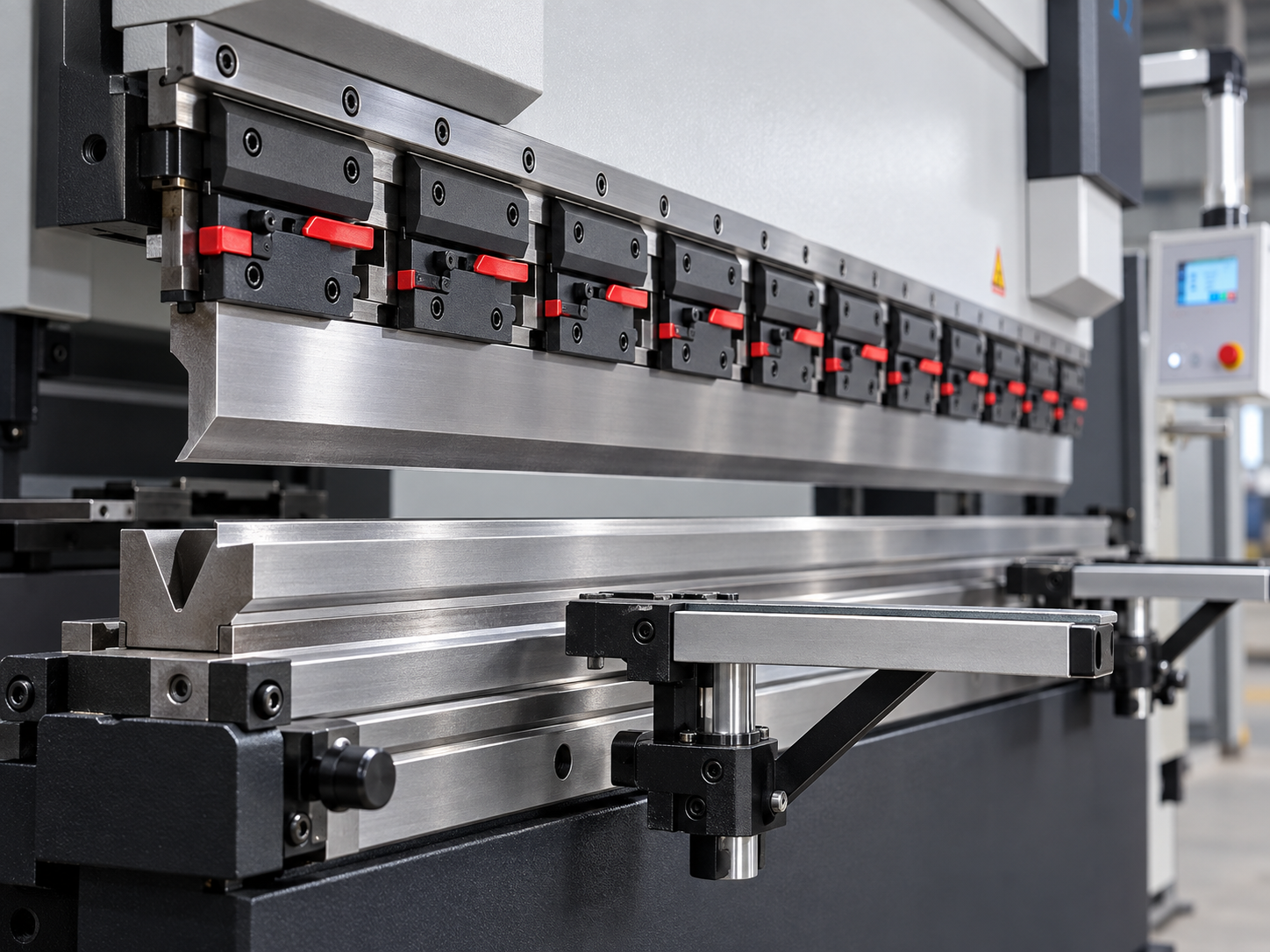
Bend allowance establishes the developed blank before forming. The first completed part then shows whether the selected bend rule matches the actual material, tooling, radius and press brake setup.
Before You Calculate, Find the Reference That Matters
Imagine a simple bracket whose flange comes off the press brake short. The first reaction is often to add material to the blank. That may hide the symptom without fixing the real mistake: the drawing was measured to an outside corner while the flat pattern was built from tangent lengths.
Start with the finished dimensions that actually control fit. Are they measured to a tangent point, an outside intersection or an assembly datum? Once that is clear, the remaining inputs have a purpose instead of becoming a checklist.
The inside radius deserves particular attention. It is the radius achieved in the part, not automatically the punch-tip radius. If the model assumes a different radius from the formed part, the blank can be wrong even when the arithmetic is correct.
Once the reference and inputs agree, the drawing itself tells you whether to add bend allowance or subtract bend deduction.
Choose the Calculation That Matches the Drawing
There is no benefit in forcing every drawing through the same route. The dimension style tells you which calculation makes sense.
BA = bend allowance · θ = angle through which the material is bent · R = inside radius · K = K-factor · T = material thickness
When the drawing uses tangent lengths
Add bend allowance to the straight sections. This is the cleanest route when the drawing or CAD model clearly identifies where the straight flange ends and the bend begins.
When the drawing uses outside dimensions
BD = 2 × OSSB − BA
Subtract bend deduction from the two outside flange dimensions. Use the same angle convention throughout and make sure both dimensions run to the theoretical outside intersection. Do not mix this route with tangent dimensions. Radius and thickness must also use the same unit.
The following 90° example uses both routes on the same bracket so you can see why they should reach the same flat length.
Worked 90° Bend Calculation
This example demonstrates the arithmetic; it does not prescribe a universal K-factor. Production values must be confirmed for the actual material, tooling and forming method.
Inside radius R = 2.0 mm
Bend angle θ = 90°
Demonstration value only; validate before production.
Calculate bend allowance
BA = (π × 90 / 180) × (2.0 + 0.40 × 2.0)
BA = 1.5708 × 2.8
BA ≈ 4.40 mm
If the two straight tangent lengths are 40 mm and 60 mm:
Flat length = 40 + 60 + 4.40 = 104.40 mm
Calculate from outside dimensions
OSSB = (2.0 + 2.0) × tan(90° / 2) = 4.00 mm
BD = 2 × 4.00 − 4.40 = 3.60 mm
If the outside flange dimensions are 42 mm and 66 mm, flat length = 42 + 66 − 3.60 = 104.40 mm. Both methods agree because the dimensions and angle convention describe the same geometry. If they do not agree on a real job, return to the references and inputs instead of forcing one result to match the other.
Moving from calculation to production? Once the blank and bend rule are established, review the available sheet metal bending equipment against the job’s bend length, material range and expected production demand.
How K-Factor Changes the Flat Pattern
Because the formula contains R + K × T, increasing K while radius, thickness and angle remain fixed produces a longer calculated bend allowance. Reducing K moves the assumed neutral axis toward the inside surface and shortens the developed arc.
That does not mean K-factor should be the first adjustment whenever a flange measures incorrectly. A short flange may come from an achieved radius different from the model, an unfinished bend angle, a gauging difference or a dimension measured from the wrong reference.
Treat K-factor as part of a proven process, not as a magic correction number. If a value produced acceptable parts on a repeat job, keep it connected to the material, thickness and forming setup that made it work. Before saving or changing that value, confirm what the first formed part is actually telling you.
When the First Part Is Wrong, Do Not Blame K-Factor First
A mathematically consistent flat pattern can still miss the finished dimension. The pattern is not always the cause, so let the symptom guide the check.
If the problem points to machine setup, calibration or equipment condition rather than the unfolding calculation, use CNC Laser Durban’s CNC technical support route.
For the next stage, the sheet metal bending machine selection guide explains how material, bend length, tooling, control and production requirements affect equipment choice.
When the angle, datum and material condition are controlled and the finished dimension repeats, the result is ready to become workshop data.
Record What Made the First Part Work
A successful blank is only valuable on the next job if the workshop knows what produced it. There is no need for a large form inside the article. A concise job record is enough:
Identify the job: drawing number and revision.
Keep the bend rule in context: material, thickness, inside radius and the K-factor or bend-table source.
Close the loop: calculated blank, critical finished dimension, first-part result and any approved correction.
For repeat production: retain the tooling or setup reference used for the approved part.
This prevents a correction from becoming an unexplained number that gets copied into unrelated jobs.
Planning a Press Brake Application?
If you are comparing press brake equipment, send a representative drawing together with the material, thickness, longest bend and expected production volume. CNC Laser Durban can use that job context to discuss a more relevant machine and tooling direction.