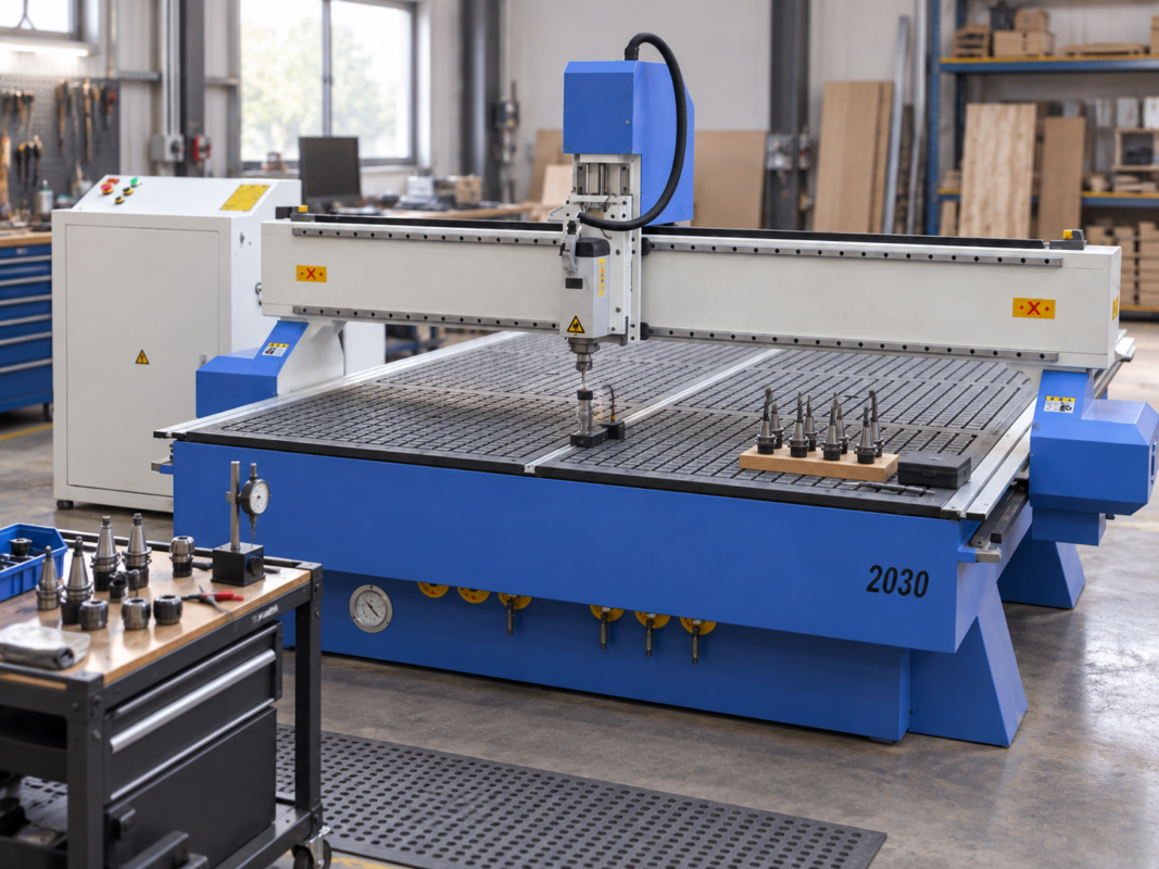
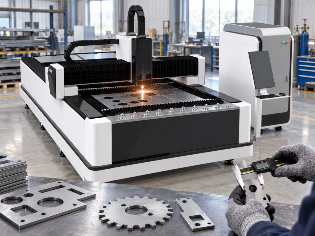
Two CNC plasma machines cutting the same thickness of plate can produce very different edges. A useful CNC plasma cut chart setup explains that difference through the actual power source, consumables, travel speed and torch height—not a universal list of numbers.
For a workshop running a CNC Plasma Cutting Machine, the starting reference comes from the installed plasma source and torch. The question is whether those settings deliver consistent results on the material and parts the workshop actually cuts.
A straight test cut, followed by a controlled speed change, often tells more than a long list of recommended values. Once the result can be repeated, the shop has a baseline it can trust—and a clearer way to assess whether its current equipment meets production needs.
A useful cut chart stays tied to the actual machine configuration rather than becoming a generic thickness-and-speed table.
What the chart is really recording
A setting only means something when its operating condition is known
Machine condition
Power source, torch, consumables and process supply.
Programmed inputs
Amperage, travel speed, pierce height and cut height.
Observed result
Penetration, cut-face behaviour, dross and repeatability.
Why One Cut Chart Does Not Suit Every Plasma Setup
A cut chart is only meaningful for the hardware it was written around. The installed plasma power source, torch and consumables determine which current range, air or gas requirements and process sequence apply. Those details come from the equipment documentation, not the plate thickness alone.
A copied setting can look convincing until a different nozzle, electrode or process supply changes the cut. Even machines working with similar plate may be operating under different process conditions.
That is why the starting reference needs the material and thickness alongside the actual consumable and source identification. Without them, a speed adjustment may be compensating for an incompatible setup rather than improving the cut.
Keep the machine configuration identifiable when recording a shop baseline.
Start with what is physically installed
The chart should describe this setup, not an abstract plasma process
Consumables that look similar are not necessarily intended for the same operating condition. Record the nozzle and electrode identification used for the test rather than writing only an amperage value.
Air or gas condition belongs in the same record. If the plasma system specifies supply requirements, verify those before trying to correct an unstable result with speed or height changes.
Why Amperage Is More Than a Thickness Setting
Plate thickness alone cannot determine amperage. The power source and the compatible torch consumables define which current settings are appropriate, so the first comparison should use a complete process combination specified for the installed equipment.
Where the manufacturer provides different process options for the same material, each represents its own combination of current, consumables and speed. Borrowing one number from each may create settings that have never been validated together.
During the first speed and height tests, keep amperage fixed. Changing current and travel speed together may change the finished edge, but it removes the evidence needed to tell which adjustment produced the change.
Keep the original reference visible.
A shop record is more useful when it distinguishes the documented starting amperage from any setting later accepted through on-machine validation.
What Travel Speed Reveals About the Cut
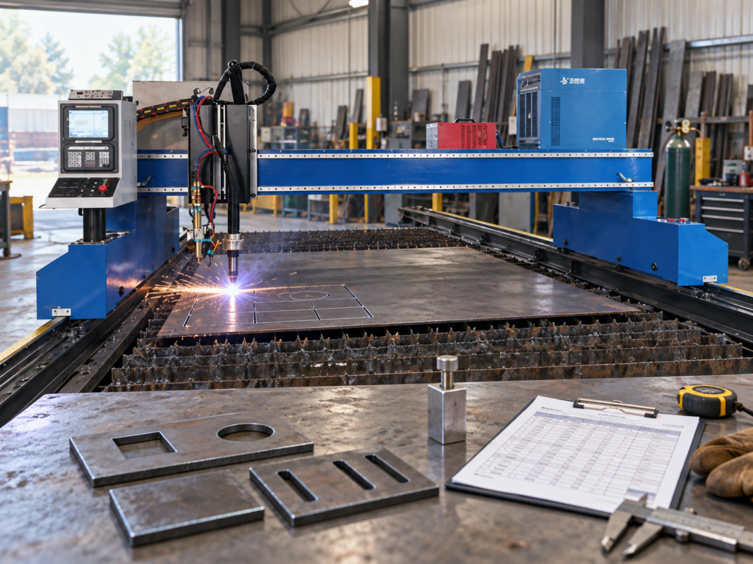
A straight test cut often reveals more about travel speed than a busy nest of corners and small features. Changes in acceleration and direction complicate the result; a simple path makes it easier to see what the plasma process itself is doing.
When material, consumables, amperage and torch height stay constant, the resulting edge gives a more useful comparison. Full penetration, kerf consistency, drag lines and underside dross should be considered together; no single symptom explains the entire cut.
Penetration
Does the arc continue to cut through the material consistently along the test path?
Kerf consistency
Does the cut remain visually stable, or does the result change along otherwise similar geometry?
Cut face
Record the visible drag pattern and its direction of change rather than labelling the sample only “good” or “bad”.
Underside condition
Note changes in attached material or dross, but do not assume one symptom proves a single cause.
Consider two straight test cuts made on the same material with the same amperage, consumables and torch height, but different travel speeds. If one produces less underside dross while maintaining full penetration, that difference is worth testing again. If repeated cuts at identical settings produce inconsistent results, further speed changes are unlikely to explain the variation; the process condition needs attention.
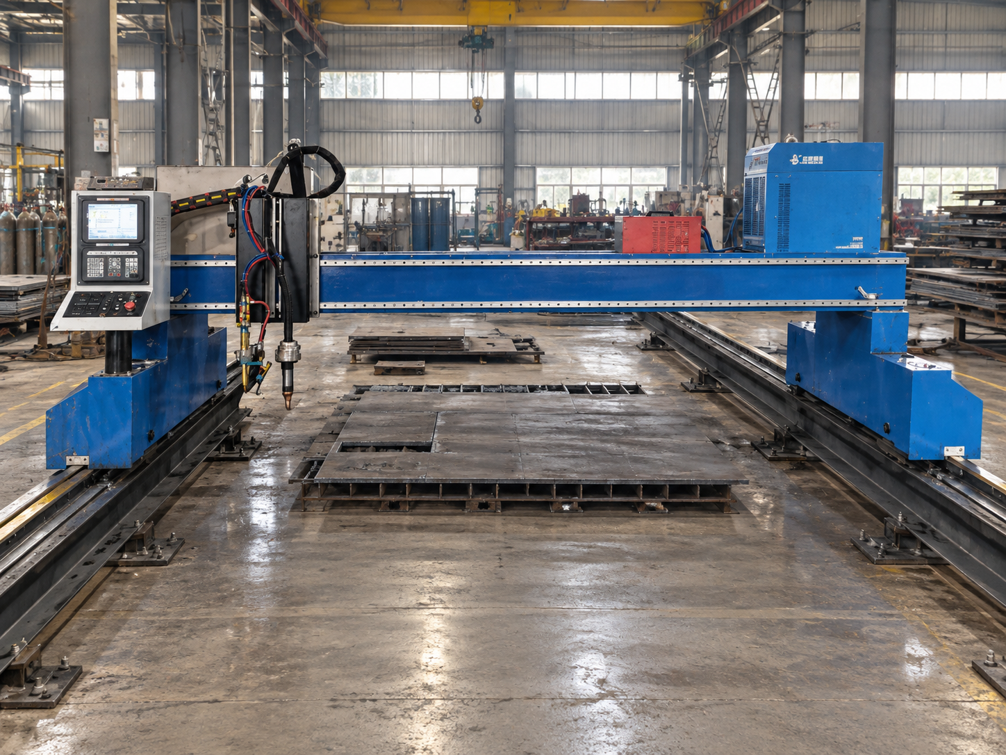
The same evidence matters when comparing equipment. The LM40120HD gantry plasma cutting machine is one model worth evaluating against your normal plate size, thickness range and production volume. Before comparing cut charts, confirm which plasma source, controller and torch-height system are supplied with the machine.
Torch Height and Pierce Sequence
Torch-height problems are easily mistaken for speed problems. The torch operates at different positions while piercing and cutting: pierce height applies as the arc penetrates the plate, while cut height applies once the cut is under way. Where fitted, torch-height control may then regulate the distance during movement.
This also explains why a height value copied from another controller can be misleading. Sensing, pierce position, delay, transition, cut height, arc voltage and height-control enable may appear as separate controls, depending on the installed system.
Stage 01
Pierce
Record the pierce height and the relevant sequence used while the arc starts and penetrates the material.
Stage 02
Transition
Confirm how the control moves from the piercing condition to the intended cutting position.
Stage 03
Cut and height control
Record cut height and, where applicable, the arc-voltage or other height-control condition used during the test.
Machine photographs provide useful configuration context, but pierce height, cut height and height-control values must still be verified from the actual equipment and controller.
A Cut Chart Worth Using Again
A useful shop record captures enough information to reproduce the test later. That means storing the physical setup and the observed result beside the programmed values instead of saving only amperage and speed.
Record
What belongs in the shop chart
Material / thickness
Material description and actual thickness used for the test.
Power source
Exact installed plasma source or identification needed to select the correct process data.
Consumables
Nozzle, electrode and other process parts needed to identify the fitted setup.
Amperage / speed
Starting values plus any later setting accepted through controlled validation.
Pierce height / delay / cut height
Record pierce height, pierce delay and cut height separately, together with the relevant height-control state.
Arc voltage
Reference or control value where the installed system uses it.
Observed result
Penetration, kerf consistency, cut-face behaviour, underside condition and repeatability.
Date / operator
Enough traceability to compare the result after maintenance, consumable replacement or process changes.
Avoid vague comments such as “better” or “bad”. A note such as “full penetration maintained; underside attachment reduced; repeat sample matched” gives the next operator far more useful evidence.
How to Know Whether a Change Worked
An edge may improve after several settings change at once, but there is no reliable way to know which change helped. Testing one variable at a time makes the result easier to trust.
01
Save the baseline
Record the exact starting condition before making the first change.
02
Change one input
Repeat the same geometry with only the variable being investigated changed.
03
Repeat before accepting
A promising result becomes useful only when the same setup can reproduce it.
If the change improves the intended result, keep it as the next baseline and move to the next variable. If it worsens the cut, return to the previous condition rather than trying to rescue the test with another simultaneous adjustment.
This also helps separate plasma behaviour from machine-motion behaviour. A stable straight test combined with inconsistent small features may indicate that the next investigation belongs somewhere other than the basic amperage, speed and torch-height baseline.
When the Cut Chart Is Not the Problem
Parameter adjustment should stop when the process stops behaving predictably. If identical settings produce noticeably different cuts, or controlled changes do not produce a logical response, the problem may no longer be the cut chart.
Move the investigation back to the machine
Stop changing numbers when the physical process is no longer stable
Confirm that the installed consumables are the intended parts and inspect their condition.
Check torch assembly against the applicable equipment information.
Verify the process gas or compressed-air condition and work connection.
Confirm that height sensing and machine movement are repeatable.
Resolve inconsistent hardware or process behaviour before continuing fine adjustment.
Persistent bevel, dross or other edge-quality faults can require a dedicated diagnostic process. A shop cut chart should preserve a proven starting condition; it should not be forced to compensate for worn parts or an unstable machine condition.
Frequently Asked Questions
What equipment information should be confirmed before building a cut chart?
Confirm the plasma power source, torch and consumables, material and thickness, process gas or air requirements, and the controller or torch-height-control system. These determine which process information is relevant to the test.
Should amperage and travel speed be changed at the same time?
No. Use amperage as a verified starting input for the installed power source and consumables. Then evaluate travel speed while keeping amperage fixed. Changing both together makes the result much harder to interpret.
Are pierce height and cut height the same?
No. They apply to different stages of the cutting sequence and should be recorded separately. Exact terminology, values and transition behaviour depend on the installed controller and plasma system.
How should validated cut-chart settings be recorded?
Record the material, thickness, power source, consumables, amperage, travel speed, pierce height, cut height, height-control condition, observations, date and operator. Keep the previous proven baseline instead of overwriting it.
When should parameter tuning stop and hardware be checked?
Stop when identical settings produce inconsistent results, controlled changes no longer create a logical response, or the process becomes unstable. Check consumables, torch assembly, process supply, work connection and height-control behaviour before continuing.
For workshops comparing plasma options
Find a Plasma Setup That Fits Your Work
The right machine is the one that handles your regular plate sizes, thickness range and production workload—not simply the highest amperage on a specification sheet. CNC Laser Durban offers plasma table and gantry options that can be compared around those requirements.
If you already have test cuts, bring the settings and sample photographs into the discussion. Whether you are reviewing an existing process or planning another machine, real cutting requirements are a better starting point than a generic chart.
To discuss a suitable setup, share:
material and thickness range · largest plate size · typical part drawings · expected workload · current machine or sample-cut details (if available)