How to Choose a CNC Wood Router for Furniture and Cabinet Production

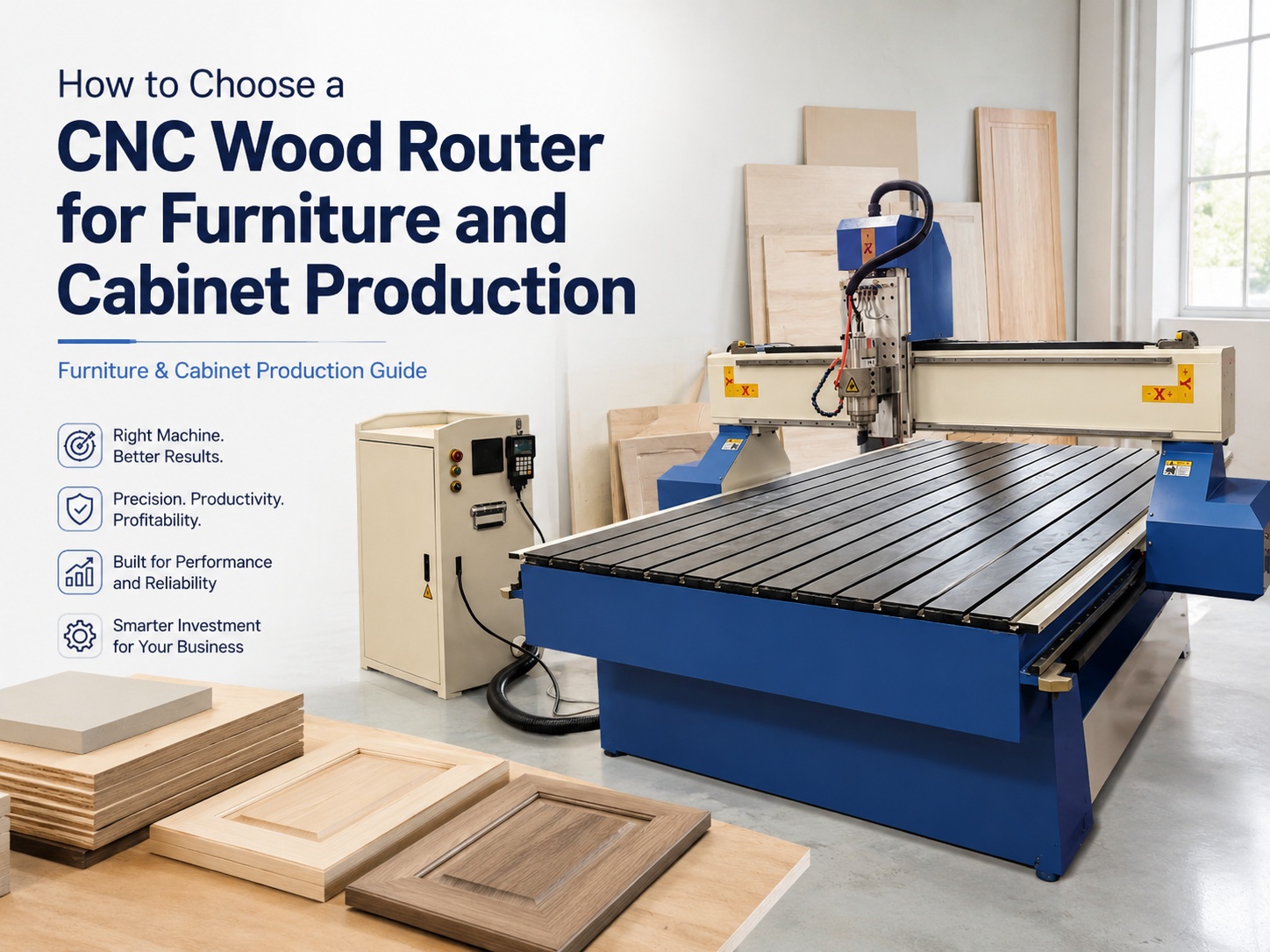
A suitable CNC Wood Router must match the complete production flow, not only the largest available machine frame. First, define regular panel sizes, material types, daily output, machining operations and tool changes. Then compare usable table area, hold-down performance, spindle configuration, software workflow, dust extraction and training. Cabinet production usually prioritises dependable sheet processing and repeatable drilling. Furniture work often requires broader tooling, deeper profiling and flexible fixtures. Therefore, the strongest selection starts with actual drawings, representative materials and a production-focused demonstration.
Direct Selection Answer: Match the Machine to the Production Method
The most reliable selection begins with the way components move through production. A cabinet workshop focused on nested sheet cutting normally needs stable panel holding, efficient file preparation and repeatable drilling or grooving. In contrast, a furniture operation may process solid timber, shaped panels, door components and smaller batches.
Therefore, machine size should follow the largest routine workpiece rather than an occasional oversized project. An unnecessarily large table increases floor use, spoilboard cost and vacuum demand. However, an undersized table creates repositioning, extra setup time and greater alignment risk.
Next, list every operation required on a normal component. Cabinet panels may need profiling, shelf-pin holes, hinge pockets, grooves, rebates and assembly marks. Furniture parts may add deeper pockets, shaped edges, carving and several cutter changes.
Daily capacity also needs a practical definition. Sheets per shift may suit a cabinet line, while parts per batch may suit a furniture workshop. In either case, the calculation should include loading, alignment, machining, tool changes, unloading, sorting and cleaning.
Software compatibility must remain part of the same decision. Existing cabinet libraries, CAD files, nesting methods and post processors can influence output every day. Consequently, a capable mechanical platform may still create delays when file preparation remains complicated.
The available router machine range should therefore be compared against a written process list. That list should separate essential functions, useful upgrades and work that will remain on other equipment.
Six questions to answer before comparing models
- Which sheet materials and solid timbers enter production every week?
- What are the regular panel dimensions and maximum component sizes?
- Which drilling, grooving, pocketing, profiling and shaping operations are essential?
- How many sheets, components or completed units must move through one shift?
- How many cutters are required during a representative production job?
- Which operator, programming and maintenance skills are already available?
Which production setup should compare each option?
|
ROUTINE PANEL CUTTING Prioritise usable table area, reliable sheet alignment, practical clamping and simple file changeover. Tool-changing complexity may remain limited when most jobs use one main profile cutter. |
NESTED CABINET PRODUCTION Focus on vacuum performance, small-part stability, drilling requirements, nesting software and complete sheet-cycle time. Sorting and labelling should also fit the production flow. |
|
MULTI-TOOL DOOR WORK Compare automatic tool changing when profiling, drilling, grooving and pocketing regularly occur within one program. Tool capacity should follow the actual tool schedule. |
CUSTOM FURNITURE PARTS Prioritise fixture flexibility, vertical clearance, cutter access and repeatable setup. A representative demonstration should include shaped parts rather than only full sheets. |
These production profiles provide a starting point, not a fixed model recommendation. Two workshops may process similar materials but use different software, fixtures and downstream equipment. Therefore, the final specification must reflect the complete operation.
The most useful early comparison is not which model has the largest specification. Instead, it is which configuration removes the most frequent production constraint. That question keeps the selection focused on measurable output.
Production Workflow, Panel Sizes and Daily Capacity
A machine purchase should be evaluated from the drawing stage through to assembly. Looking only at cutting speed hides many production delays. For example, material storage, sheet loading, part identification and edge banding may control the final output.
In cabinet production, approved drawings often become cut lists, nested layouts and machining programs. After routing, parts may move to labelling, edging, hardware preparation and assembly. A weakness at any stage can reduce the value of faster machining.
Furniture production may follow a less uniform route. Some components begin as sheet goods, while others begin as solid timber blanks. In addition, shaped components may require roughing, finishing, drilling, sanding and manual fitting.
Consequently, the production map should show every repeated movement. Material should move from storage to loading, machining, unloading and the next operation without unnecessary crossing. A simple floor sketch often exposes delays before equipment is ordered.
Group work into part families
First, separate the workload into practical part families. Flat cabinet panels form one group. Doors, drawer fronts, rails, legs, mouldings and decorative pieces form additional groups.
Each group should identify the raw material, finished dimensions, machining operations and required cutters. Moreover, the list should show whether components need two-sided work, raised fixtures or edge access.
This process reveals which operations belong on the routing machine and which remain elsewhere. For example, some hardware operations may occur after edge banding. Likewise, some furniture components may still need drilling, sanding or edge-finishing equipment.
Small parts deserve special attention. Narrow cabinet strips, drawer components and furniture rails may lose holding force as surrounding material is removed. Therefore, the test file should include difficult components rather than only large panels.
Confirm nominal size and usable working area
A machine description does not always show the complete usable cutting area. Tool clearance, gantry limits, clamping zones and safety margins can reduce practical travel. Therefore, nominal dimensions and programmed movement should be confirmed separately.
Purchasing records provide the best source for panel planning. Regular MDF, plywood, particleboard and laminated-board formats should come from actual orders. Oversize wardrobe sides or architectural panels should appear in a separate column.
This distinction prevents an occasional format from controlling the full specification. A larger machine may be justified when oversize work occurs regularly. However, infrequent work may be handled through another production method.
Material thickness also affects the working envelope. Thin panels may flex, while thick blanks reduce available vertical clearance. In addition, fixtures, long cutters and raised workholding consume part of the available height.
Therefore, the complete vertical stack should include the table surface, spoilboard, fixture, material and cutter. A component can fit within the machine frame while still exceeding safe programmed movement.

The PS 1318 can be included when a more compact working format is being compared for regular panels, signs, templates or furniture components. Final suitability should follow actual part dimensions and operations.
Calculate output from the complete cycle
Daily capacity should not be estimated from feed rate alone. The complete cycle includes loading, alignment, hold-down activation, tool changes, cutting, drilling, unloading and cleaning.
For example, a nested cabinet sheet may contain many small components. The program may finish quickly, yet sorting and labelling can delay the following sheet. Similarly, a furniture part may require a short cut but a long fixture setup.
Therefore, a representative time study should record each repeated step. It should also include normal pauses, tool checks, material changes and routine cleaning. Continuous movement without interruption is rarely a realistic shift model.
Peak demand deserves attention as well. Average monthly output may hide short periods when kitchens, wardrobes or contract furniture must move quickly. However, the capacity plan should still use achievable staffing and operating conditions.
A strong demonstration should run a normal production file from loading to finished parts. The test should show file selection, origin setting, tool changes and unloading. A simple outline cut provides little evidence for a production decision.
Plan material flow around the machine
The machine must fit within a working production cell. Sheet racks need a clear route to the loading side. Finished components need space for removal, identification and transfer.
Meanwhile, extraction ducts, electrical cabinets and service points require access. A frame that fits on a floor drawing may still create congestion during real production. Service clearance should therefore remain visible on the layout.
Manual sheet handling may suit a lower-volume operation. In contrast, sustained panel production may justify trolleys, lifting aids or another loading method. The decision depends on board weight, handling frequency and available floor space.
Finished parts should move away from incoming material. Crossing traffic increases confusion and edge damage. In addition, waste and offcuts need a defined route that does not block the next loading cycle.
A one-direction layout often improves production control. Material enters from one side, completed components leave from another, and sorting occurs outside the machine zone. Even when space is limited, clear routes reduce unnecessary handling.
Plan for realistic growth
Future demand should influence the decision, although speculative work should remain separate from confirmed production. Likely increases in cabinet volume may justify faster changeovers or improved loading flow.
Growth planning should focus on probable changes. Examples include larger wardrobe panels, additional drilling operations, more door designs or a second shift. These changes can be discussed against the proposed control, table and tooling arrangement.
In contrast, an uncertain possibility of occasional unusual work should not define every feature. Otherwise, the project can become more complex without improving normal production.
Material capability also requires clear limits. A woodworking routing platform should not be treated as a general metal machining centre. Any unusual material must be confirmed for the specific configuration, tooling and operating method.
Table Size, Spoilboards and Vacuum Hold-Down
Table selection affects more than maximum panel length. It influences sheet loading, vacuum zoning, spoilboard maintenance, fixture access and waste removal. Therefore, the complete workholding system should be reviewed as one production unit.
A large table provides little value when parts cannot remain stable during the final passes. Likewise, a powerful vacuum source cannot compensate for an uneven spoilboard or uncontrolled leakage. Each part of the system must support the others.
Understand the spoilboard
A spoilboard is a sacrificial layer placed above the main table surface. It allows the cutter to pass slightly through sheet material without damaging the machine bed. A suitable porous board may also distribute vacuum beneath the workpiece.
The surface must remain flat, clean and correctly prepared. Deep grooves, damaged corners and accumulated dust increase leakage. Consequently, hold-down can weaken even when the pump remains in good condition.
Resurfacing removes grooves and restores an even plane. However, repeated resurfacing reduces board thickness. Therefore, the operating plan should include the correct surfacing tool, replacement point and cleaning procedure.
Loose chips beneath a panel also create problems. They can prevent full contact and introduce depth variation. In addition, hard debris may mark a finished surface during loading.
Test difficult components, not only full sheets
Vacuum hold-down creates a pressure difference beneath the workpiece. Large panels normally provide more surface area for holding force. Small parts and narrow strips provide less area and may move as surrounding waste disappears.
Therefore, a demonstration should include the smallest regular components. It should also include long narrow parts, internal cut-outs and small offcuts. These features reveal weaknesses that a full uncut sheet will not show.
Porous materials can increase leakage. MDF core quality, plywood construction and spoilboard condition all influence the result. In addition, warped sheets may prevent an even seal across the table.
Cutting order can improve stability. Internal holes, pockets and grooves usually occur before the outside profile releases a component. Smaller parts may also remain connected until later in the cycle.
An onion-skin strategy leaves a thin material layer during an early profile pass. A later pass removes that layer after the main machining is complete. This method can reduce movement, although the correct approach depends on material and finish requirements.
Tabs provide another option by leaving small connections between a component and surrounding stock. However, tab removal adds labour and may require sanding or trimming. The reduced movement risk should therefore be compared with the added finishing time.
Review vacuum zoning and leakage control
Vacuum zoning allows unused table areas to be isolated. For example, a smaller sheet may only require one section of a larger bed. Closing unused zones can reduce unnecessary leakage and improve practical holding.
Zone layout should match routine panel sizes. The control method should also remain clear during a shift. Incorrect valve or switch positions can weaken holding without an obvious visual warning.
Dedicated fixtures may use gasket material to seal a smaller area. This method can suit repeated furniture components or shaped blanks. However, gasket channels, support points and tool clearance require careful planning.
A strong seal does not guarantee a stable component. Unsupported areas may still flex under cutting pressure. Therefore, fixture support and vacuum sealing should be assessed together.
Ask for a complete vacuum-system explanation
The phrase “vacuum table” does not describe complete performance. The proposed configuration should identify the pump arrangement, zone controls, spoilboard requirement and routine maintenance.
Pump evaluation can include airflow, duty cycle, noise, heat and service access. However, exact sizing must remain tied to the proposed machine and workload. Generic figures from another system provide limited value.
Pipework position also affects workshop planning. Long routes, leaks and restrictive fittings may reduce effective performance. Meanwhile, heat and noise can influence where the pump should sit.
Therefore, the installation drawing should show the machine, vacuum equipment and connections. This prevents a later layout change from creating avoidable restrictions.
Consider clamps and fixtures for specialised work
Vacuum is not the only holding method. Mechanical clamps, screws, dedicated jigs and raised fixtures may suit special components. For solid furniture parts, a repeatable fixture can provide reliable location and support.
However, every clamp must remain outside the programmed cutter path. Safe Z heights, fixture drawings and simulation become important. Clear setup instructions should accompany repeated jobs.
Raised pods may provide edge access beneath a component. Nevertheless, pod position, collision risk and part stability require careful programming. The complete setup height must also remain within safe clearance.

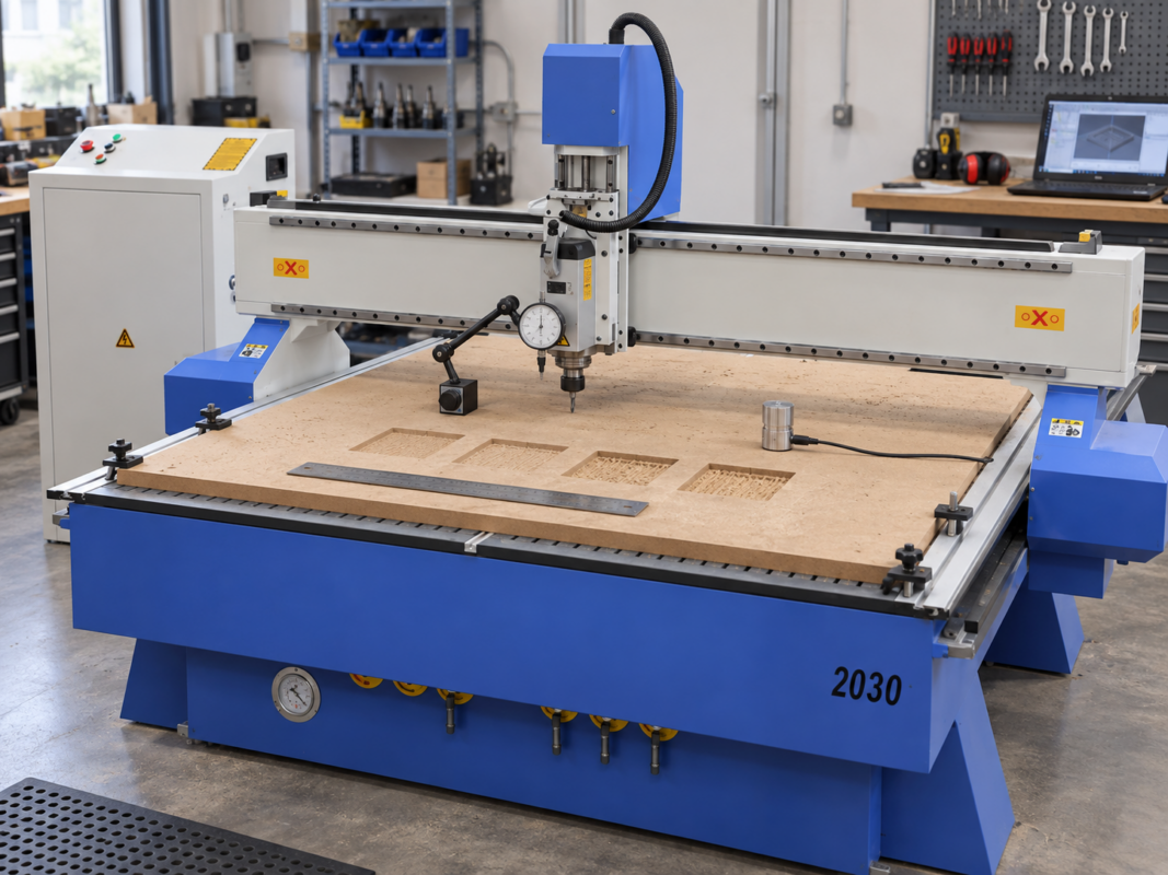
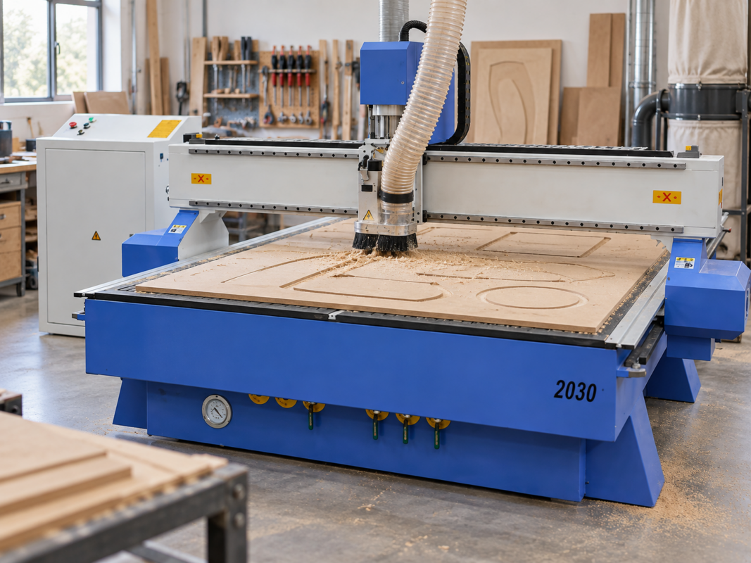
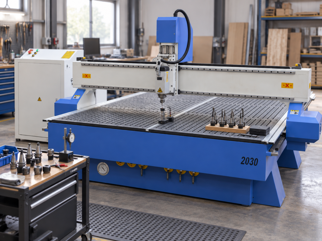
The PS 2030 is relevant when a larger working format and different hold-down arrangements need to be compared. Final suitability should be confirmed against regular panel sizes and the intended production process.
Test the proposed setup with a representative file
A useful demonstration should include normal sheet loading, small nested parts, relevant tool changes and a dimensional check. A simplified outline does not provide enough production evidence.
Spindle Configuration, Tooling and Tool Changing
The spindle drives the cutter, although its power rating does not describe the whole cutting process. Tool diameter, material density, cutting depth, feed rate, spindle speed and machine structure all interact.
Therefore, spindle selection should start with the heaviest regular operation. Cabinet work may involve grooves, drilling and full-depth profiles. Furniture work may add deeper pockets, shaped edges and longer finishing toolpaths.
Duty cycle matters as well. A spindle used continuously across a production shift faces different demands from one used for occasional batches. The proposed configuration should therefore match both cutting load and operating pattern.
Build the tool list from actual drawings
A tooling discussion should begin with component drawings. Every hole, groove, pocket, profile and edge detail should connect to a cutter. Consequently, the required tool count becomes clear before tool-changing options are compared.
Upcut spiral tools move chips upward and can support chip removal. However, an unsuitable setup may damage the upper surface of laminated material. Downcut tools push cutting action downward and may protect the top face.
Compression cutters combine upward and downward cutting sections. When selected and positioned correctly, they can support clean top and bottom edges on suitable laminated boards. Cutter geometry, entry depth and material thickness must align.
Straight cutters, drills, ball-nose tools, engraving tools and profile cutters serve different operations. Cutter diameter also affects internal corner radius and cutting force. A smaller tool reaches tighter details but may require shallower passes.
A larger tool can remove material efficiently, although it cannot produce small internal radii. Therefore, tool size should follow drawing geometry and required finish rather than cutting speed alone.
Compare manual and automatic tool changes
A manual tool-change arrangement may suit work that uses one cutter for most of the cycle. It can reduce system complexity. However, every change stops production and introduces another setup step.
Automatic tool changing can support jobs that move between drilling, grooving, pocketing and profiling. Cabinet doors and mixed furniture components may require several cutters during one program.
Nevertheless, a large tool rack does not automatically improve output. If most jobs use one main cutter, many unused stations provide limited value. The normal tool schedule should therefore define the required capacity.
Tool rack position matters as well. A station placed outside the cutting area can preserve table space. Meanwhile, dust protection and cleaning affect reliable tool changes.
A demonstration should show a complete change sequence. It should include tool selection, offset handling, spindle restart and recovery after interruption. These details reveal daily usability more clearly than a static machine inspection.
Confirm tool measurement and offset control
Different cutters have different lengths. The control system needs accurate tool-length information to maintain programmed depth. Some arrangements use a measurement sensor, while others require additional setup procedures.
Tool numbers should remain consistent between the CAM software, machine program and physical rack. A mismatch can select the wrong cutter. Therefore, naming rules and verification steps should be established before production begins.
Collet and tool-holder condition also affects finish quality. Dust, wear or incorrect tightening can increase runout and reduce cutter life. Cleaning and inspection should form part of routine maintenance.
Cutter extension requires attention as well. Excessive extension may increase vibration and reduce stability. Conversely, insufficient clearance can create a collision risk during deeper work.
Treat feeds and speeds as an application process
Feed rate describes movement through material. Spindle speed describes cutter rotation. Chip load connects those values to the number of cutting edges.
These factors should create proper chips rather than heat and rubbing. An unsuitable feed can cause burning, fuzzy edges, chatter or premature wear. Increasing rotational speed alone may not solve the problem.
Starting settings should come from approved tooling guidance and application testing. Final settings should reflect the actual material, cutter and finish requirement. One value rarely suits every board grade.
Plywood veneers, MDF density, adhesive layers and hardwood grain can change cutting behaviour. Therefore, a controlled tool library should store proven starting points for each regular material.
Sound, chip form, edge quality and cutter temperature provide useful feedback. Burn marks may indicate rubbing or poor chip removal. Chatter may point to tool extension, holding or cutting-load problems.
Confirm specialised operations separately
Some cabinet workflows need horizontal drilling, specialised heads or additional machining operations. These functions should not be assumed from a general product description. Each operation should be shown on a drawing and confirmed against the proposed setup.
Deep carving and raised components also require clearance checks. A workpiece may fit on the table but still exceed safe vertical movement once the fixture and cutter are included.
Door production may combine pocketing, profiling, engraving and edge finishing. Drawer components may prioritise small-part holding and repeatable drilling. Consequently, several representative files provide stronger evidence than one simple sample.

The PS 1930 automatic tool changer is relevant for comparison when cabinet or furniture programs require several repeated cutter changes. Tool capacity and operation suitability should be confirmed against representative production files.
Control Software, File Preparation and Training
A routing machine follows the instructions supplied to its control system. Therefore, software fit can influence productivity as strongly as the mechanical platform. The full process may include design, CAM preparation, nesting, post processing and machine control.
CAD software creates drawings or models. CAM software converts geometry into toolpaths. A post processor translates those toolpaths into commands that match the selected controller.
Although one program may combine several stages, their functions remain different. Understanding those functions helps isolate errors and define support responsibilities.
Begin with the current design environment
Established design practices should be documented before new software is introduced. A cabinet operation may already use product libraries, cut lists and hardware rules. A furniture workshop may rely on general CAD, templates or parametric models.
Therefore, the review should identify current file formats, nesting methods and export steps. It should also determine whether existing data can produce reliable machining output.
Replacing every existing process may create unnecessary disruption. Instead, the technical review should identify which stages already work and which stages cause delays.
Cabinet databases need careful control. Material thickness, edging, hardware positions and drilling rules may repeat across many parts. One incorrect rule can therefore affect an entire project.
General CAD offers flexibility for custom furniture and one-off work. However, toolpath preparation may require more manual input. Programming hours should therefore appear in the production calculation.
Test the post processor with the proposed controller
A post processor must match the controller and machine configuration. Generic output may not handle tool changes, drilling commands or safe movements correctly.
Therefore, representative files should be posted, simulated and run during the approval process. A successful file import does not confirm the complete workflow.
The test should include rapid moves, spindle commands, tool calls, drilling, pockets and final profiles. Start and end positions should also be observed carefully.
Program origin must remain consistent. Some workflows use a fixed table reference, while others use a workpiece corner or fixture point. Either method can work when setup instructions remain clear.
Mixing several origin methods across similar jobs increases risk. Therefore, the programming standard should define when each method applies and how it is checked.
Create a repeatable file-preparation checklist
A consistent checklist protects quality and machine safety. First, confirm drawing units, material thickness and finished-face orientation. Next, review grain direction, component spacing and part labels.
Then check every cutter, tool number, cutting depth and toolpath order. Lead-ins and entry moves should avoid visible finished edges where possible.
Tabs or onion-skin passes should match the hold-down plan. Safe Z heights must clear the workpiece, fixtures and clamps. Consequently, the setup sheet should connect programming choices to the physical table arrangement.
Internal machining normally occurs before outside profiling. Holes, pockets and grooves remain stable while the component still belongs to the sheet. The final profile then releases the part.
Part spacing should balance material yield and process stability. Very tight nesting may improve theoretical yield but leave weak strips between components. The best layout is not always the layout with the least unused material.
Use simulation and first-article inspection
Simulation can reveal missing tools, incorrect depths and unsafe movements before cutting begins. However, digital simulation cannot confirm actual holding, cutter condition or finished dimensions.
Therefore, the first physical component remains an essential approval step. Overall dimensions, hole positions, groove widths and pocket depths may need measurement.
Edge finish and surface marks should also be reviewed. Only after the first component meets the drawing should the full batch continue.
Measurement records support process improvement. If the same dimension changes across several jobs, the cause may involve tooling, material, calibration or file preparation.
Control file names, revisions and backups
Program names should connect to a job, product and revision. Clear naming reduces the chance of running an outdated file. Approved programs should also remain separate from drafts and test versions.
Machine settings, tool libraries and post processors need backups. A workstation problem should not remove the only copy of a proven production process.
Therefore, the backup method should include secure storage, revision dates and a defined responsibility. File recovery should also be tested before it becomes necessary.
File transfer should suit workshop conditions. Network transfer may support central control, while removable storage may suit another environment. In either case, uncontrolled copies can create conflicting versions.
Make training specific to production roles
General machine orientation provides a useful start. However, production training should use actual cabinet or furniture files. Operators need to load material, establish references, select tools and manage normal pauses.
Programming roles need a different focus. Tool libraries, nesting rules, post processing, simulation and revision control require practical attention.
Maintenance roles need clear daily and scheduled tasks. Cleaning, spoilboard care, collet inspection, lubrication checks and extraction inspection should form part of the routine.
Training requirements should be included in the enquiry sent through the demonstration and training enquiry page. The scope should identify the production files, operating roles and maintenance topics that need to be covered.
In addition, the CNC machine technical support page covers setup, calibration, control systems, software-related issues, repairs and planned maintenance. These services should be discussed as part of the complete installation plan.
Dust Extraction, Workshop Requirements and Buying Checklist
Routing produces chips and fine dust, so extraction belongs in the main machine specification. Poor capture can affect visibility, surface cleanliness, hold-down performance and tool life.
Required extraction depends on material, cutter, removal rate, duct route and operating cycle. A system suitable for occasional work may not suit continuous cabinet production.
Likewise, a large extraction unit may still perform poorly when the hood, branches or connections restrict airflow. Therefore, the complete system should be reviewed rather than one power figure.
Capture dust near the cutting point
A dust shoe surrounds the cutter area and connects to the extraction duct. Its brush or skirt should remain close enough to collect chips. However, it must not interfere with clamps, raised components or tool changes.
Duct routing has a major effect on performance. Long runs, sharp bends, leaks and unsuitable branches reduce effective airflow. Consequently, the final machine position should allow a practical connection path.
MDF creates fine dust, while plywood and laminated panels produce mixed chips and particles. Solid timber may create larger chips depending on the cutter and operation.
Therefore, filtration, collection and cleaning procedures should match the actual material mix. South Africa’s official Regulations for Hazardous Chemical Agents provide relevant occupational health guidance for wood dust generated during wood-processing operations.
Workshop controls should therefore reflect the processed materials and applicable occupational health requirements. Extraction design, risk assessment, housekeeping and protective measures should be addressed through the appropriate workplace procedures.
Confirm electrical and compressed-air requirements
Electrical requirements vary with the machine, spindle, vacuum arrangement and extraction equipment. The complete connected load must therefore be confirmed for the selected configuration.
The distribution board, protection devices, cable route and isolation point may require assessment before delivery. Information from another model should not be copied into the site plan.
Some configurations also require compressed air for tool changing or accessories. Required pressure, flow and air quality should appear in the installation information.
Moisture and contamination can affect pneumatic components. Consequently, an existing workshop air line should not be assumed suitable without verification.
Correct earthing and stable supply conditions also matter for industrial controls. Exact requirements should come from the approved documentation for the proposed system.
Check delivery access and service clearance
The delivery route should be measured from the property entrance to the final position. Door widths, ceiling height, turning space and floor condition may affect installation.
Lifting equipment also needs suitable access. Therefore, the machine footprint alone does not complete the delivery plan.
Service clearance should remain around electrical cabinets, pumps and moving assemblies. Placing equipment tightly against a wall may save space at first but complicate later maintenance.
Material racks and finished-part areas need space as well. Incoming sheets should not block the operating position or service panels. Finished parts should move to the next process without crossing the loading route.
Furniture and cabinet selection table
| Selection area | Information to collect | Why it affects the decision | Evidence to request |
| Panel dimensions | Regular length, width, thickness and oversize formats | Defines usable table area, loading method and nesting margin | Written usable travel and a full-sheet test |
| Daily output | Sheets, parts or completed units per shift | Influences loading, tool changing, software and extraction | Timed cycle using a representative file |
| Operations | Profiling, drilling, grooving, pocketing and shaping | Defines spindle, tooling, clearance and accessory needs | Sample drawing reviewed operation by operation |
| Materials | MDF, laminated board, plywood, particleboard and timber | Affects cutters, dust control, settings and holding | Test cuts in regular production material |
| Tool list | Cutter types, diameters, drills and profile tools | Determines manual or automatic change requirements | Tool schedule linked to a normal job |
| Tool changing | Changes per program and changes per shift | Affects cycle interruption and operating consistency | Live change sequence and recovery procedure |
| Vacuum holding | Large sheets, smallest parts, narrow strips and porous boards | Defines zoning, spoilboard practice and final-pass strategy | Nested test containing difficult small components |
| Dust extraction | Material mix, duty cycle, duct route and collection method | Affects cleanliness, visibility, holding and maintenance | Connection and extraction requirements |
| Software | Design tools, file formats, nesting and post processing | Controls programming time and compatibility | End-to-end test from drawing to finished part |
| Training | Operator, programmer and maintenance responsibilities | Reduces setup errors and supports stable production | Written training scope using real files |
Practical demonstration agenda
A useful demonstration should begin with a representative drawing or program. The file should contain normal operations, several component sizes and at least one difficult narrow part.
Next, the material should be loaded using the proposed method. The demonstration should show alignment, origin setting, hold-down activation and file selection.
The machining cycle should include relevant tool changes, drilling, pocketing and profiling. Extraction performance and part stability should remain visible throughout the test.
If a normal pause or alarm occurs, the recovery procedure should be explained. Recovery is part of real production and should not remain outside the demonstration.
After cutting, selected components should be measured. Hole positions, grooves, outside dimensions and edge quality should be compared with the drawing.
Finally, the discussion should cover file preparation, routine maintenance, training and technical support. A demonstration request can include material type, panel dimensions, required operations and expected shift output.
Final pre-order checklist
Production and capacity
|
Table and holding
|
Spindle and tooling
|
Software and control
|
Installation and support
|
Commercial confirmation
|
Common selection mistakes
One common mistake is choosing only by table size. A large bed does not guarantee suitable holding, software or tooling. The complete production process must remain visible.
Another mistake is comparing only spindle ratings. A larger figure does not automatically create a better edge or faster cycle. Tool geometry, cut strategy and machine structure still matter.
Programming time is also easy to underestimate. A short cutting cycle may follow several hours of file preparation. Software templates, product libraries and repeatable post processing therefore deserve careful review.
Dust extraction may be postponed until the machine position is already fixed. This can create long duct routes and poor service access. Instead, extraction should influence the layout from the beginning.
Generic training creates another risk. A basic overview may not cover cabinet databases, nesting rules or furniture fixtures. Training should use representative production files and defined responsibilities.
Finally, broad material claims should be treated carefully. Any unusual application requires written confirmation, suitable tooling and a controlled test. Unverified capability should not appear in a production forecast.
Frequently Asked Questions
Further Reading and Support
Router Machine RangeReview the current routing range before comparing table layouts, tool-changing options and application requirements. |
Technical SupportExplore support information covering setup, calibration, troubleshooting, repairs and planned maintenance. |
South African CNC OverviewReview the company’s broader machinery, training and support offering for industrial production in South Africa. |
Final Selection Summary
A strong routing investment begins with production evidence. Table dimensions, hold-down performance, spindle configuration, tooling and software must operate as one process. Extraction, training and support should also fit the workshop layout and available skills.
Before approving a CNC Wood Router, complete three practical actions:
- Document the workload: record materials, panel sizes, part families, operations, tool changes and realistic shift output.
- Run a representative demonstration: include real files, narrow parts, relevant tooling and dimensional checks.
- Confirm the complete scope: record the configuration, installation requirements, training and support in current written documents.
Request a Production-Focused Demonstration
Include the regular material, panel dimensions, required operations, tool list and expected shift output. A representative test provides clearer evidence for machine selection and workshop planning.