Aluminium Welding Machine Guide: Laser Welding for Aluminium Fabrication

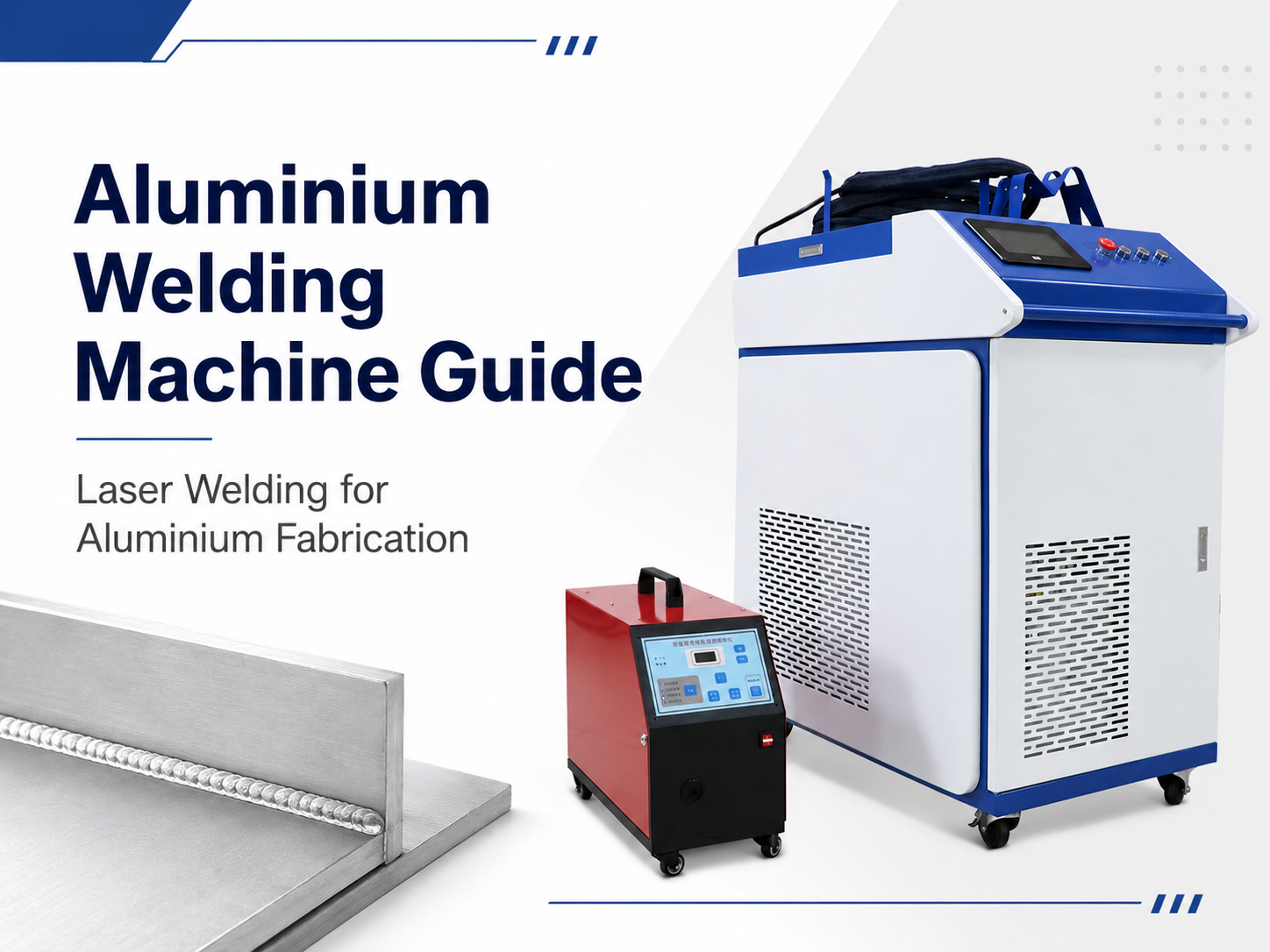
Laser welding can join selected aluminium parts when the equipment, alloy and process conditions are suitable. However, suitability should not be assumed from a general demonstration. An Aluminium Welding Machine must be assessed against the actual grade, thickness, joint, surface condition and quality target. Aluminium reflects laser energy, conducts heat quickly and develops a persistent oxide film. Therefore, stable production depends on controlled preparation, shielding, fit-up and parameter testing. A representative sample trial remains the most reliable starting point before production approval.
Can a Laser Welding System Handle Aluminium?
The direct answer remains conditional. A suitable laser system may weld aluminium, but the result depends on the complete application. Laser power alone does not confirm feasibility. Beam delivery, process controls, welding-head configuration, filler delivery and shielding arrangements also influence weld stability.
In addition, the material must be identified accurately. Different alloy families respond differently during fusion welding. Material temper, product form, coating, cleanliness and previous forming operations can also change the available process window.
Therefore, equipment evaluation should begin with the actual component rather than a broad material description. A statement such as “two-millimetre aluminium” leaves several important questions unanswered. The material could be commercially pure sheet, a magnesium-bearing plate or a heat-treatable extrusion.
Joint geometry matters just as much. A straight lap seam, outside corner, fillet and square butt joint create different heat-flow and fit-up conditions. Likewise, a sealed enclosure needs different validation from a decorative cover or lightly loaded bracket.
The required result must also be defined before testing begins. Some components mainly need a neat external seam. Others require structural strength, leak resistance, dimensional control, internal penetration or fatigue performance.
Without measurable acceptance criteria, a visually attractive bead can create false confidence. Surface appearance does not confirm internal fusion, low porosity or retained strength. Consequently, inspection planning should form part of the initial application review.
Four Questions That Need Practical Evidence
- Can the proposed configuration start and maintain a stable weld on the specified alloy?
- Can the process achieve the required fusion without unacceptable burn-through or edge collapse?
- Can the result be repeated across realistic material, gap and operator variation?
- Can the completed joint meet the required appearance, dimensions, strength and leak standard?
Each question requires evidence. A short demonstration on an unidentified offcut does not establish a production process. Instead, representative coupons and complete parts should be welded under recorded conditions.
Furthermore, the trial should include normal manufacturing variation. Material from more than one batch can reveal differences in cleanliness and surface condition. Several starts, stops and seam lengths can also expose problems hidden by one short sample.
A conditional answer is not a weakness. Rather, it reflects sound industrial decision-making. Aluminium welding performance depends on a connected set of variables, not one brochure statement or one favourable demonstration.
Why Aluminium Is Challenging to Laser Weld
Aluminium can appear straightforward because it is common, light and easy to machine. Nevertheless, fusion welding introduces several connected challenges. Reflectivity, rapid heat movement, oxide contamination, hydrogen porosity and alloy-related cracking all require control.
Reflectivity During Weld Initiation
At room temperature, aluminium reflects a significant portion of commonly used industrial laser radiation. As a result, weld initiation can be less forgiving than many steel applications. The process must establish effective energy coupling before a stable molten region develops.
Once absorption increases, the surface response can change quickly. Therefore, an unstable start may be followed by sudden melting. This transition can contribute to inconsistent penetration, local surface damage, spatter or edge loss.
However, reflectivity alone does not determine success. Beam quality, focus position, travel speed, oscillation pattern and joint alignment all influence energy transfer. Consequently, the complete process configuration must be tested rather than judged only by the laser source.
Surface finish can also change initial behaviour. Bright mill-finished stock may respond differently from brushed, oxidised, anodised or coated material. Even adhesive residue from protective film can disturb an otherwise stable seam.
Independent technical guidance from TWI on aluminium joining technology also identifies reflectivity and high thermal conductivity as important process considerations. Therefore, controlled testing remains more useful than relying on a general material label.
Rapid Heat Conduction and Low Melting Temperature
Aluminium moves heat away from the weld zone quickly. At the same time, its base material melts at a comparatively low temperature. This combination creates a narrow balance between insufficient fusion and excessive local melting.
Too little effective energy can leave incomplete penetration or weak sidewall fusion. Conversely, excessive local energy can cause burn-through, undercut, edge collapse or an oversized molten region.
Thin sheet requires particular care. Heat can spread through a panel and alter its shape, especially along long or asymmetric seams. Although concentrated welding may reduce total heat input, fixture design and welding sequence still affect distortion.
Thicker sections create a different problem. More energy may be needed for penetration, yet molten-metal behaviour must remain controlled. Therefore, thickness should never be considered separately from joint type, access and filler requirements.
Sections with changing mass can behave unevenly. For example, a seam moving from a thin flange into a heavy boss experiences different heat flow. Fixed settings may not suit both areas, even when the alloy remains unchanged.
The Natural Oxide Layer
Aluminium naturally develops a protective oxide film after exposure to air. This film supports corrosion resistance, but it complicates welding. The oxide melts at a much higher temperature than the underlying aluminium.
Consequently, a thick, hydrated or contaminated oxide layer can interfere with puddle formation. It may also contribute to poor fusion, porosity and inconsistent bead appearance.
A clean-looking surface is not automatically weld-ready. Fingerprints, cutting fluid, storage residue, moisture and workshop dust can remain difficult to see. Likewise, extrusion lubricant may remain close to the joint after cutting.
For consistent production, preparation should follow a written sequence. The same tools, solvents and timing should be used during sample testing and later production. Otherwise, a successful trial may not transfer reliably.
Hydrogen-Related Porosity
Porosity remains a major concern in aluminium fusion welding. Hydrogen can dissolve in molten aluminium, then become less soluble during solidification. Trapped gas can therefore form internal pores inside the weld metal.
Potential hydrogen sources include moisture, oil, grease, dirty filler wire and contaminated gas delivery. Poor storage can also introduce condensation onto sheets, profiles or consumables. As a result, porosity control begins before the welding head reaches the joint.
Not every pore carries the same consequence. Small internal pores may be acceptable in one lightly loaded component but unacceptable in another. Pressure-retaining, fatigue-loaded or highly stressed assemblies may need stricter inspection.
Therefore, the acceptance standard should be defined before samples are produced. Otherwise, inspection may identify indications without providing a clear pass-or-fail decision.
Cracking and Local Property Changes
Some alloy combinations have greater solidification-cracking sensitivity than others. Joint restraint, filler selection and final weld chemistry can influence this risk. A successful seam on one grade cannot prove suitability for another.
Heat-treatable alloys create an additional concern. Welding may alter properties inside the fusion zone and surrounding heat-affected area. Consequently, the completed joint may not retain the original parent-material strength.
This issue matters when drawings specify a particular temper. The design may rely on properties achieved through heat treatment or work hardening. Welding can change those properties locally even when the bead appears smooth.
Accordingly, structural work may require engineering review, procedure qualification or mechanical testing. Visual inspection alone cannot verify every performance requirement.
Where This Type of System May Fit
Laser welding is usually most attractive when the component, fixture and workflow support a repeatable seam. Close fit-up, controlled access and stable surface preparation create a better starting point than irregular repair work.
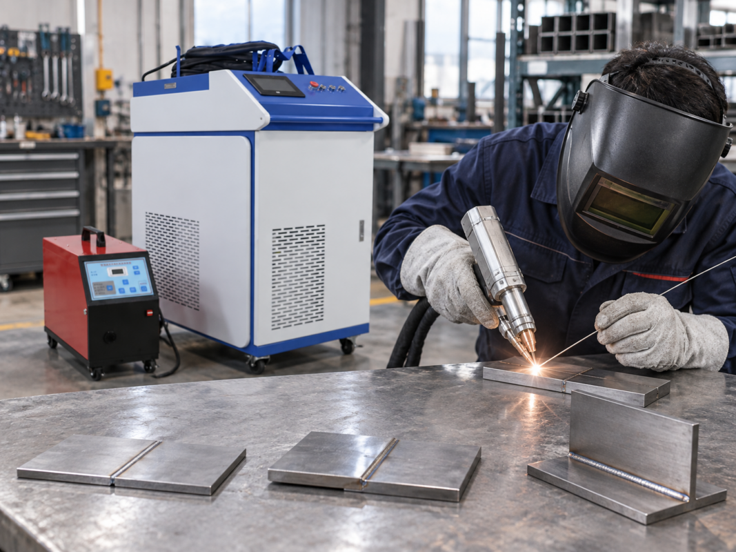
The CNC Laser Durban product page lists aluminium alloy among the possible weldable materials for its fibre laser welding, cleaning and cutting system. However, the exact grade, joint, thickness and quality target still require confirmation through a representative test using the proposed configuration.
Applications Worth Testing
- Repetitive sheet-metal seams with consistent joint gaps
- Aluminium cabinets, covers and industrial enclosures
- Frames and profile assemblies made from verified alloys
- Visible seams where reduced finishing may add value
- Thin-wall tubes and formed parts with suitable access
- Production work supported by fixtures and repeatable cleaning
Applications Requiring Extra Caution
- Unknown or mixed aluminium grades
- Large, irregular or changing joint gaps
- Heavy structural joints needing substantial filler metal
- Outdoor repairs with uncontrolled shielding conditions
- Safety-critical components without qualified testing
- Parts requiring certified mechanical performance

The product should appear within the decision process rather than interrupt it. Therefore, the equipment page becomes most useful after the application has been described clearly. The next step is not an immediate purchase decision, but a structured suitability review.
A material certificate can remove major uncertainty during that review. It may confirm alloy designation, temper and product form. Without traceability, parameters may be developed for the wrong material, while later production batches behave differently.
A simple identification system helps prevent confusion. Each test coupon can carry a batch reference, alloy, temper and measured thickness. Corresponding parameter records should use the same reference.
Product form should also be recorded. Sheet, plate, extrusion and cast material can have different surface conditions and heat-flow behaviour. Consequently, identical alloy numbers may still require different preparation or parameters.
Common Alloy Families
Alloy series provide a useful starting point, but they do not create a complete welding procedure. Temper, product form, service conditions and joint geometry still require review.
| Alloy family | Common fabrication context | Items requiring confirmation |
|---|---|---|
| 1xxx series | Commercially pure sheet, electrical components and general fabrication | Required strength, cleanliness, penetration target and distortion limit |
| 3xxx series | Sheet products, enclosures, tanks and formed parts | Exact grade, fit-up, appearance standard and filler requirement |
| 5xxx series | Marine, transport and structural sheet applications | Magnesium content, filler compatibility, service temperature and corrosion exposure |
| 6xxx series | Extrusions, profiles, frames and general structures | Temper loss, cracking sensitivity, filler choice and post-weld strength |
| 7xxx series | High-strength components and specialised structures | Exact grade, fusion weldability, cracking risk and engineering approval |
| Cast aluminium | Housings, repaired components and complex shapes | Casting chemistry, existing porosity, contamination, wall variation and repair history |
Mill Finish, Anodising and Coatings
Mill-finished stock often carries oils, marks or storage contamination. Therefore, degreasing remains important even when the surface appears bright. A clean appearance does not confirm a clean joint.
Anodising creates a controlled oxide coating. This finish may interfere with welding and may need local removal. However, the removal method should match the cosmetic requirement and corrosion-protection plan.
Paint, powder coating and conversion coatings also require assessment. Residue near the seam can create fumes, contamination and poor fusion. Accordingly, coated parts should not enter testing without a defined stripping procedure.
Protective plastic film presents another practical risk. The film may stop before the joint, yet adhesive can remain near the edge. The sample trial should reproduce the actual film-removal and cleaning sequence.
For a broader overview of available handheld laser welding solutions, the product category provides the relevant starting point before technical questions and sample material are submitted.
Joint Preparation, Shielding and Filler Strategy
Reliable aluminium welding begins before energy reaches the component. Joint preparation, fit-up, clamping, shielding and filler strategy must work together. A weakness in one area can reduce the value of otherwise suitable settings.
Create a Repeatable Cleaning Sequence
A practical preparation sequence starts with material identification. Next, protective films and visible contamination should be removed. Degreasing can then address oil, fingerprints and cutting-fluid residue.
After degreasing, oxide removal may be required by the approved procedure. Dedicated tools help prevent cross-contamination from carbon steel. The preparation method should remain consistent across every test coupon.
The order matters because mechanical cleaning can spread oil across the surface. Therefore, removing hydrocarbons before brushing or abrasion normally creates a more controlled baseline.
Tools should remain dedicated to aluminium. A brush previously used on steel may introduce foreign particles. Likewise, worn or dirty abrasives can spread contamination instead of removing it.
After preparation, the parts should remain clean and dry. Excessive delay can allow new contamination or moisture exposure. Consequently, preparation-to-weld time should form part of the work instruction.
Compressed air also requires caution. Air lines can carry oil or water when filtration is poor. Therefore, compressed air should not be treated as automatically suitable for final cleaning.
Control Joint Gap and Edge Alignment
Laser welding generally rewards consistent fit-up. A narrow and concentrated heat source may not bridge large or irregular gaps. Therefore, component tolerance should be measured before process approval.
A square butt joint often needs accurate edge alignment. Misalignment can leave insufficient fusion on one side. Meanwhile, changing gaps can alter bead shape, penetration and filler demand.
Lap joints can offer more tolerance in selected assemblies. However, trapped contamination between sheets remains a concern. Overlap length and clamping pressure also influence heat movement.
Outside corners may produce narrow and attractive seams when edges remain consistent. Nevertheless, thin corners can melt back quickly. The trial should therefore include the minimum expected edge thickness.
Fillet joints introduce another challenge. The beam must reach the intended fusion line while suitable torch access remains available. Filler may also be necessary when the joint volume exceeds the available parent metal.
Fixtures should hold the joint without creating excessive restraint. Strong restraint can control movement, but it may increase stress in crack-sensitive combinations. Accordingly, fixture design must balance alignment and restraint.
Fit-Up Information to Record
- Nominal and maximum joint gap
- Edge mismatch and part flatness
- Fixture contact and clamp positions
- Tack size, spacing and sequence
- Torch access and angle restrictions
- Start, stop and run-off conditions
Treat Shielding Gas as a Process Variable
Shielding gas protects the molten region from atmospheric contamination. However, gas type alone does not guarantee coverage. Nozzle position, flow, leaks and workshop draughts also matter.
The suitable gas arrangement should come from the proposed machine configuration and verified procedure. No general recommendation should replace application testing. Gas purity and delivery-system cleanliness also need confirmation.
More gas flow is not automatically better. Excessive velocity can create turbulence and draw surrounding air into the shielding zone. Conversely, insufficient flow can leave the molten area exposed.
The trial should therefore record actual flow settings, nozzle distance and torch angle. It should also reproduce realistic movement rather than a fixed laboratory position.
Draughts deserve special attention in industrial premises. Open roller doors, extraction systems and portable fans can disrupt shielding. Consequently, sample testing should consider the intended working environment.
Decide Whether Filler Wire Is Necessary
Autogenous welding joins the parent material without added filler. This approach can suit tightly fitted joints where chemistry and joint volume allow it. However, it does not suit every alloy or geometry.
Filler wire may help bridge a controlled gap, build the required profile or modify weld-metal chemistry. It can also support joints where additional metal is needed. Nevertheless, an unsuitable filler can introduce cracking, corrosion or strength concerns.
Therefore, filler selection must consider both parent materials and the service environment. A wire chosen only because it feeds smoothly may not provide the required joint performance.
Wire diameter and entry angle affect delivery. In addition, the wire must reach the correct location in the molten zone. Poor alignment can create an uneven bead or intermittent deposition.
Wire cleanliness remains important. Oxide, lubricant or moisture can enter the weld through the consumable. Accordingly, storage, handling and preparation should form part of the test procedure.
Plan for Distortion
A concentrated process may reduce total heat input in suitable work. However, no thermal joining method eliminates distortion automatically. Thin panels, long seams and asymmetric assemblies can still move.
Fixture design provides the first control, while welding sequence provides the second. Therefore, sample components should be measured before and after welding.
Balanced sequencing, staged clamping or intermittent welding may help. Yet each method can change cycle time and joint appearance. Dimensional control should therefore be considered during process costing.
The heat-affected zone also deserves attention. A narrow zone may be beneficial, but local property changes can still occur. A narrow bead should never be treated as proof of retained strength.
Parameter Testing and Sample Validation
Parameter testing converts general machine capability into application evidence. Therefore, the test should be planned rather than improvised. Representative material, realistic joints and measurable acceptance criteria must all be available.
The purpose is not merely to produce one neat seam. Instead, the exercise should determine whether the process remains stable across expected variation. It should also identify the controls needed for production.
Start With a Written Application Brief
A useful brief describes the component and its function. It should also define the consequence of failure. A cosmetic blemish, a leak and a structural fracture carry different risks.
Drawings should identify weld length, location and access. Where formal drawings are unavailable, marked photographs can support discussion. Nevertheless, dimensions and material details should still be supplied separately.
Expected production quantity also matters. A low-volume repair task may justify a different setup from a repetitive manufacturing line. Likewise, prototype work may accept more manual adjustment.
The brief should include downstream operations. Machining, anodising, painting and pressure testing can reveal defects later. Therefore, the weld should be evaluated within the complete production route.
Use a Controlled Test Matrix
A test matrix changes one variable at a time where practical. This method helps identify cause and effect. Random adjustment may produce a good result without explaining why it worked.
Initial screening can explore a controlled range of travel speeds and energy settings. Focus position and oscillation settings may also require review where the proposed equipment supports them.
When filler wire is used, feed rate becomes another variable. Shielding flow and nozzle position should remain recorded. Likewise, joint gap and surface preparation must not change unnoticed.
The sequence should include start, steady-state and stop behaviour. Short coupons can hide defects at seam ends. Therefore, some samples should reproduce the full production seam length.
Corners and direction changes also need attention. Handheld motion can slow at a corner and increase local heat. Complex parts should not be represented only by straight coupons.
Aluminium Project Confirmation Table
The following table provides a practical framework for technical review, demonstration and quotation. Each item should be confirmed before a sample is treated as representative.
| Confirmation item | Information to record | Why it affects the decision | Evidence required |
|---|---|---|---|
| Alloy grade | Exact designation, temper and product form | Chemistry and temper influence fusion behaviour, cracking and post-weld properties | Material certificate or verified purchase specification |
| Material thickness | Nominal thickness and tolerance range | Thickness changes penetration, heat flow and burn-through risk | Drawing, measurements and representative coupons |
| Joint type | Butt, lap, fillet, corner, tube or mixed joint | Geometry changes access, fit-up tolerance and required weld volume | Drawing, photographs and physical sample |
| Joint gap | Nominal gap, maximum gap and edge mismatch | Concentrated energy may provide limited gap tolerance | Measured samples across the expected production range |
| Surface state | Mill finish, brushed, oxidised, anodised, coated or contaminated | Surface condition affects energy coupling, porosity and stability | Clean and worst-case samples with preparation records |
| Appearance requirement | Bead width, colour, finish and visible-seam standard | Cosmetic limits may restrict oxidation, undercut and filler profile | Approved reference sample or documented visual standard |
| Strength requirement | Static load, fatigue demand, impact or engineering specification | Visual quality does not confirm mechanical performance | Defined test method and pass criteria |
| Leak requirement | Air, water, gas or process-fluid containment | Small discontinuities may fail containment service | Pressure, medium, duration and test method |
| Filler wire | Alloy, diameter and feeding arrangement | Filler changes chemistry, gap tolerance and bead shape | Application recommendation and trial result |
| Shielding gas | Gas type, purity, delivery method and flow range | Poor shielding can increase contamination and porosity | Recorded setup and verified gas delivery |
| Fixture method | Clamp positions, backing, tack sequence and heat sinks | Fixturing affects alignment, restraint and distortion | Production-representative fixture or documented equivalent |
| Cycle expectation | Weld length, quantity, handling and duty pattern | A short demonstration does not establish production output | Timed test including loading and repositioning |
| Inspection method | Visual, sectioning, bend, tensile, leak or other approved testing | Different defects require different detection methods | Agreed inspection plan and acceptance criteria |
| Sample validation | Quantity, material batches and repeated runs | Repetition reveals process and operator sensitivity | Labelled samples, setting records and inspection results |
This table should travel with the sample material. It gives the technical team a clear basis for preparation. More importantly, it prevents assumptions from filling missing application details.
Inspect More Than the Surface
Visual inspection remains useful. It can reveal undercut, excessive oxidation, inconsistent width, spatter and poor starts. However, it cannot confirm internal fusion or porosity.
Cross-sectioning offers valuable evidence during process development. A prepared macro section can show penetration depth, fusion shape and internal discontinuities. Therefore, destructive sectioning should be considered for representative coupons.
Bend testing may reveal lack of fusion or cracking in suitable specimens. Tensile testing can support structural evaluation. Nevertheless, test selection must match the joint and service requirement.
Leak testing is essential when containment matters. The selected method should reflect operating pressure, test medium and service conditions. A simple visual check cannot confirm a sealed assembly.
Surface inspection methods may identify surface-breaking discontinuities. However, they cannot reveal every internal defect. Inspection methods should therefore be combined when application risk justifies additional testing.
Record Settings and Physical Conditions
A repeatable process needs a detailed record. Therefore, every accepted sample should carry a setting sheet. The record should include both machine configuration and preparation details.
Minimum Test Record
- Machine and welding-head identification
- Programme or parameter-set reference
- Energy setting and measured travel speed
- Focus, standoff and oscillation arrangement
- Wire type, diameter and feed setting
- Shielding gas, flow and nozzle position
- Surface preparation and preparation-to-weld time
- Joint gap, alignment and fixture arrangement
- Operator, sample number and material batch
- Inspection result, photograph and approval status
Environmental conditions may also matter. High humidity, open-air exposure or strong airflow can affect cleanliness and shielding. Unusual test conditions should therefore be noted.
A saved machine programme alone is insufficient. The result also depends on preparation, handling and technique. The work instruction should connect settings with physical process controls.
Test Repeatability, Not Only Possibility
One acceptable coupon establishes possibility. Several acceptable coupons begin to establish repeatability. Accordingly, the trial should include multiple samples and repeated starts.
Where practical, more than one material batch should be included. This step reveals sensitivity to surface condition or composition variation. It also prevents approval based on unusually clean stock.
Different operators can test ergonomic tolerance. A process that only works with one highly experienced operator may require tighter control, improved fixtures or further training.
Longer seams should also be included when production requires them. Heat accumulation and hand movement can change over distance. Tubes and box sections may also trap heat differently from flat coupons.
Arrange a Representative Sample Test
Prepare the verified alloy grade, thickness, joint drawing, surface condition and acceptance requirements. A controlled trial can then determine whether the proposed configuration deserves further production evaluation.
When MIG or TIG May Still Be Preferable
Laser welding can offer valuable advantages in suitable applications. Nevertheless, it should not replace MIG or TIG by default. Process selection should follow joint requirements, production volume and available controls.
MIG remains widely used for aluminium fabrication. It can support substantial filler deposition, larger joint volumes and established structural procedures. Therefore, it may remain practical for thicker sections or less precise fit-up.
TIG offers detailed manual control and a clear view of the molten pool. It can suit prototypes, repair work and lower-volume precision fabrication. However, cycle time may be longer for repetitive production.
Laser processing may support narrow seams, concentrated heat input and faster travel where fit-up remains controlled. Yet the process can be less tolerant of irregular gaps. Part accuracy and fixture design therefore become central.
| Decision factor | Laser welding | MIG welding | TIG welding |
|---|---|---|---|
| Typical use case | Repetitive seams with controlled fit-up | General fabrication and larger weld volumes | Precision, prototypes and repair work |
| Gap tolerance | Often requires close and consistent fit-up | Filler deposition can support more joint volume | Manual filler addition can manage controlled variation |
| Heat input | Concentrated in suitable joints | Usually broader, depending on transfer mode | Highly controllable but often slower |
| Travel speed | Potentially high after process development | Moderate to high | Usually lower for manual work |
| Filler addition | Optional or configuration-dependent | Integral to the process | Added manually or mechanically |
| Operator influence | Motion, angle and standoff remain important | Torch angle, stick-out and speed matter | Strongly influenced by torch and filler coordination |
| Production suitability | Strong potential for repeatable, well-fixtured work | Broad industrial suitability | Strong for specialised or low-volume work |
Situations That May Favour MIG
MIG may remain preferable when the joint requires substantial filler metal. It can also suit larger fillets and thicker structural sections. Many fabrication teams already maintain established MIG procedures.
Irregular fit-up can also favour a process with greater filler deposition. However, excessive gaps remain a quality problem under any method. Process choice should not replace dimensional control.
Long structural seams may align with existing mechanised MIG equipment. In addition, familiar consumables and inspection procedures may simplify implementation.
Field work can create another reason. Laser safety controls, equipment protection and access may be harder to establish outside a controlled area. Site conditions should therefore form part of the comparison.
Situations That May Favour TIG
TIG can suit low-volume parts requiring careful manual adjustment. It can also help during repair work where the joint changes continuously. The operator can modify filler input while observing the puddle.
Prototype development may also favour TIG. Extensive tooling and programme development may not be justified for one-off components. However, manual skill remains a major process variable.
Thin decorative work can use TIG successfully when distortion remains controlled. Nevertheless, a developed laser process may offer faster production later. Annual volume can therefore change the preferred method.
Situations That May Favour Laser Welding
Repetitive seams with consistent fit-up can create a strong case for laser processing. Concentrated heat may reduce post-weld finishing and distortion. In addition, higher travel speed may support shorter cycles.
Visible enclosures, cabinets and formed-sheet assemblies may benefit where appearance matters. However, starts, stops and corners still require testing.
Thin tubes and profile assemblies may also suit the process. Yet wall thickness, joint access and shielding must remain consistent. Actual production sections should therefore enter the trial.
A laser-based route may reduce finishing in selected work. Nevertheless, production savings should include preparation, fixturing, gas, inspection, maintenance and training.
Compare the Complete Production Route
Welding speed alone does not determine production cost. Loading, cleaning, clamping and repositioning may consume more time than the seam itself. A timed trial should include the entire cycle.
Rework must also enter the comparison. A faster process can become expensive when fit-up variation creates rejects. Conversely, improved fixtures may reduce both welding and finishing time.
Consumables differ across processes. Wire, gas, nozzles, optics and maintenance items should be identified. No cost assumption should be made without a confirmed machine configuration.
Training also influences implementation. A new process needs operating instructions, safe work procedures and maintenance knowledge. Startup planning should therefore include more than demonstration time.
Supplier Confirmation Checklist
A technical discussion should produce written answers. General marketing descriptions should not replace application confirmation. The following checklist helps organise the decision before an order or production commitment.
Machine and Process Capability
- Does the proposed configuration support the specified alloy grade?
- Which thickness and joint combinations can be demonstrated?
- Is autogenous welding suitable, or is filler required?
- Which welding head and optical arrangement will be supplied?
- Which focus and oscillation adjustments are available?
- Can approved settings be stored and recalled consistently?
- How will reflective-material risk be managed?
- Which shielding arrangement suits the proposed joint?
- What fixture accuracy and maximum joint gap are required?
- Which start, stop and corner methods are recommended?
These questions need application-specific responses. A general statement that a system processes aluminium remains incomplete. The response should connect the exact configuration to the supplied grade and joint.
Sample Testing and Acceptance
- Will the demonstration use representative production material?
- Can several coupons and full-length seams be tested?
- Will all settings and preparation steps be recorded?
- Can selected samples be sectioned or mechanically tested?
- Which defects may appear during process development?
- How will penetration and sidewall fusion be confirmed?
- Which result will establish production approval?
- Can a production operator participate in testing?
- Can the result be reproduced after installation?
- Which material or joint changes require renewed testing?
A useful trial ends with documented evidence. Without records, the workshop may struggle to reproduce the demonstration. Setting sheets and labelled samples should therefore form part of the handover.
Installation and Workshop Integration
- What electrical supply does the exact configuration require?
- Which gas supply, purity and regulator are required?
- Which extraction and ventilation controls are recommended?
- Which cooling and environmental conditions are necessary?
- How much floor space and access clearance are required?
- Which controlled-area requirements apply?
- Which protective equipment is specified?
- How should nearby reflective surfaces be controlled?
- Which materials must remain outside the operating zone?
- What daily startup and shutdown checks are required?
South African workshops may also need to consider power quality, local gas availability and service access. Installation planning should reflect the intended site rather than a showroom environment.
Electrical protection deserves particular attention. Voltage variation, earthing and surge conditions can affect industrial equipment. The exact requirements should be reviewed by competent electrical personnel.
Gas availability should also be confirmed locally. A technically suitable arrangement may become operationally inconvenient. Cylinder supply, purity, regulator compatibility and expected consumption therefore enter the decision.
Training, Maintenance and Support
- Which operator training is included?
- Does training cover preparation and defect recognition?
- Which maintenance tasks belong to the operator?
- Which optics or protective items need inspection?
- Which spare parts should remain on site?
- What support is available for parameter troubleshooting?
- How are control or software issues handled?
- Which preventative-maintenance intervals apply?
- What information is needed when reporting a weld problem?
- Can remote and on-site assistance be arranged?
CNC Laser Durban provides technical support covering equipment setup, calibration, diagnostics, repairs and preventative maintenance. However, the exact support scope for the proposed welding configuration should still be confirmed in writing.
Further information about available welding application support can assist with installation planning, maintenance responsibilities and troubleshooting preparation.
Commercial Scope
- What is included in the quoted configuration?
- Is a wire-feeding package included or optional?
- Which nozzles, lenses and protective items are supplied?
- Are installation and commissioning included?
- Is application testing included?
- Which training sessions form part of the scope?
- Which maintenance items are excluded?
- Which site-preparation tasks remain with the workshop?
- What documentation accompanies the equipment?
- What conditions apply to support and warranty coverage?
No commercial assumption should fill a missing answer. Price, delivery, warranty, accessories and included services can change. Therefore, the written quotation should identify the exact scope and the application evidence supporting it.
Frequently Asked Questions
Related Equipment and Support Resources
Product Details
3-in-1 Fibre Laser Welding System
Review the published welding, cleaning and cutting system before discussing configuration and sample requirements.
Product Category
Welding, Cleaning and Cutting Range
Use the category as the main equipment entry point before moving into a specific aluminium application review.
Technical Service
CNC Technical Support
Review setup, calibration, diagnostics, repairs and preventative-maintenance support for industrial equipment.
Final Selection Guidance
A sound decision starts with material facts rather than broad capability statements. First, confirm the exact alloy, temper, thickness and joint. Next, define measurable acceptance criteria before any demonstration begins.
Then reproduce the intended preparation, shielding, fixturing and filler arrangement. Several samples should be tested instead of selecting one favourable bead. Finally, compare the complete result with the existing MIG or TIG route.
The following three actions provide a practical route from research to an informed equipment decision:
- Prepare representative samples: Include normal and worst expected joint conditions.
- Define measurable acceptance: Record visual, dimensional, mechanical and leak requirements.
- Approve only repeatable results: Keep documented settings, preparation steps and inspection evidence.
An Aluminium Welding Machine should only be approved after the proposed configuration passes a representative and documented trial. Alloy details, joint drawings, surface condition and required results can be submitted to CNC Laser Durban before a sample test is arranged.
Ask About Aluminium Suitability
Submit the alloy grade, material thickness, joint drawing, surface condition and acceptance requirements. The application can then be reviewed before a representative test is scheduled.